09-10 Input/Output Devices
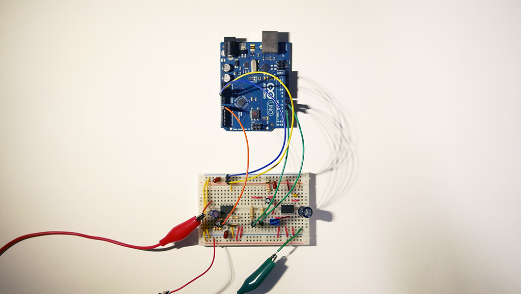
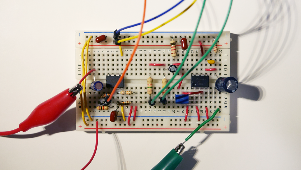
This week, I decided to start making the circuit for my final project - to build a portable/reprogrammable guitar effector using a microcontroller. Below is the prototype I built. I used Arduino UNO to verifiy my circuit design.
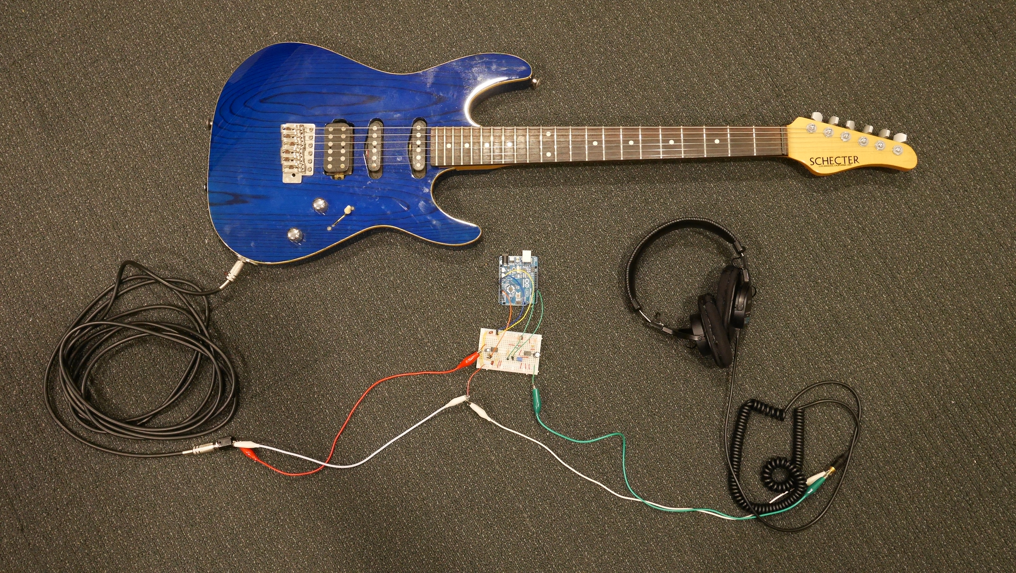
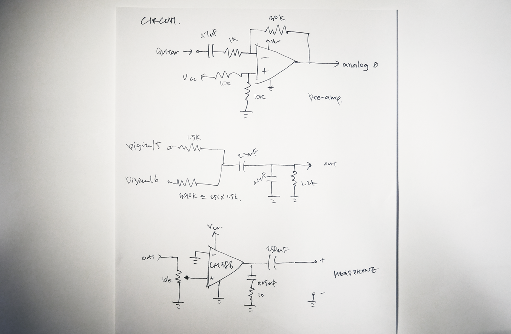
As the signal from guitar is very small I needed a preamp. Voltage offest was also needed to set the input signal within 0-5V range of Arduino. I had some difficulty offsetting the input voltage and setting the gain to a proper value. After experimenting with different sized caps and resistors I could finally get a decent input signal.
For the output, I used "weighted pins" technique for getting a higher resolution than 10-bits. Following the output stage, I put a LM386 audio amp to drive a speaker or a headphone.
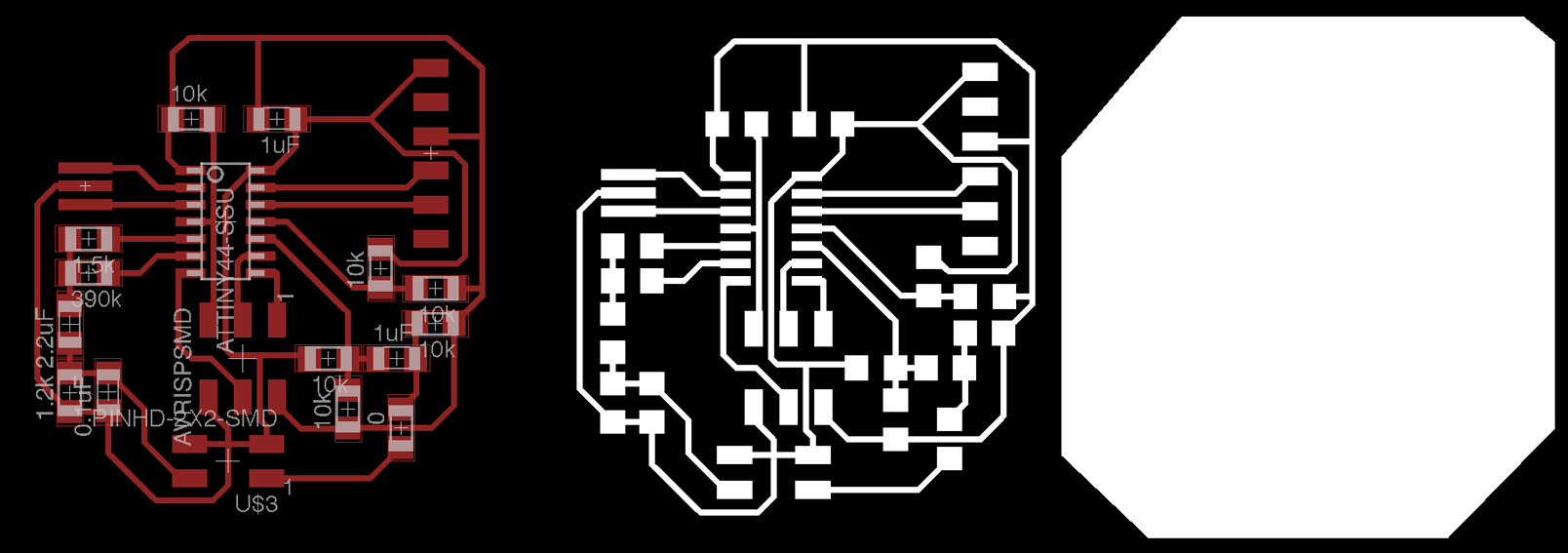
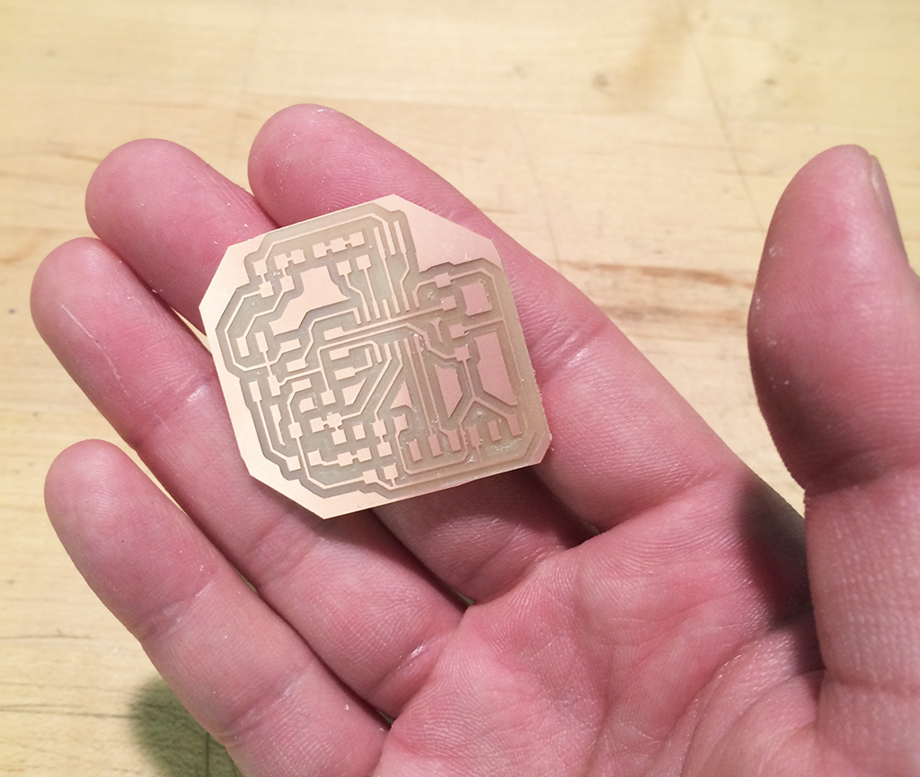
I am planning to combine this week's exploration with next week's assigment of making an output device. I will fabricate the circuit using Modela next week, as there are still circuit design problems I have to solve. I will also try with ATtiny44.
There are some potential risks and problems
1) Noise - a pcb layout might (hopefully) reduce noise, or a shielding case is needed
2) Non-linearity - the preamp I designed has some distortion.
3) Processing power - an ATtiny might not be suitable for real-time sound processing. ATmega is an option to go in such case.
4) TODO: designing sound effects.
Arduino code used below. (based on http://pastebin.com/9zphwpvA )
void setup()
{
TCCR0B = TCCR0B & 0b11111000 | 1;
TCCR0A &= ~B11;
TCCR0A |= B011;
pinMode( 5, OUTPUT );
pinMode( 6, OUTPUT );
analogWrite( 5, 0 );
analogWrite( 6, 0 );
analogReference( DEFAULT );
_SFR_BYTE( ADCSRA ) &= ~_BV( ADPS2 );
_SFR_BYTE( ADCSRA ) |= _BV( ADPS1 );
_SFR_BYTE( ADCSRA ) |= _BV( ADPS0 );
}
void loop()
{
int input = ( (analogRead( 0 ) ) * 64 ) - 32768;
if(input>=65536) input = 65535;
if(input<0) input = 0;
/* Shift the signed variables into unsigned 16-bit for output (0 ... 65535). */
unsigned short output = input + 32768;
analogWrite( 5, output >> 8 );
analogWrite( 6, output & 255 );
}
Some sound samples.
I tried a new version using ATtiny44. As ATtiny's ADC has differential mode and 20x gain mode, I suspect (as Neil's suggestion) I could made an effector with out using an external Op-Amp.
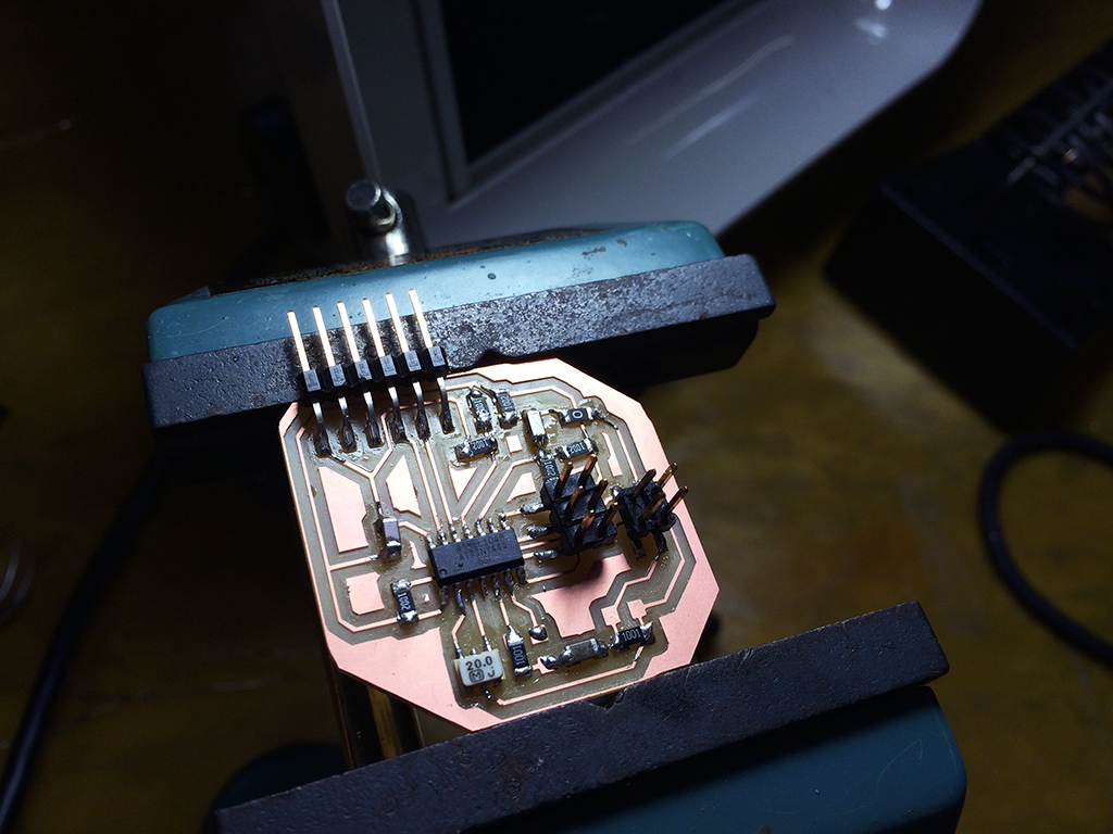
The code I used. I am still facing problems as I am not getting a perfect sound out of it. I here some distorted sound. One possible reason is the gain mismatch, thus causing clippings. The other possibility is the code.
long inputRaw, input;
void setup()
{
TCCR0B = TCCR0B & 0b11111000 | 1;
TCCR0A &= ~B11;
TCCR0A |= B011;
pinMode( 8, OUTPUT );
pinMode( 7, OUTPUT );
analogWrite( 8, 0 );
analogWrite( 7, 0 );
analogReference( DEFAULT );
/* admux */
ADMUX = (0 << REFS1) | (0 << REFS0) // 5V ref
| (1 << MUX5) | (1 << MUX4) | (0 << MUX3) | (0 << MUX2) | (0 << MUX1) | (1 << MUX0);
ADCSRA = (1 << ADEN) // enable
| (1 << ADPS2) | (1 << ADPS1) | (0 << ADPS0); // prescaler /64
ADCSRB = (1 << BIN); // bipolar mode
}
void loop()
{
/* get input */
delay(2);
ADCSRA |= _BV(ADSC); // Convert
while (bit_is_set(ADCSRA,ADSC));
inputRaw = ADCL;
inputRaw |= ADCH<<8;
input = ( inputRaw * 64 ) - 32768;
/* Shift the signed variables into unsigned 16-bit for output (0 ... 65535). */
unsigned short output = input + 32768;
analogWrite( 8, output >> 8 );
analogWrite( 7, output & 255 );
}
And the sound sample.
Copyright © 2014 Sang-won Leigh