This week we learned how to mill a printed circuit board (PCB) and surface solder components to it. We all made the same circuit a Fab ISP (in-system programmer) to be used with micro-controllers later in the semester. For this week we were given the traces and used the online fab modules to mill the circuit out. Here is the outline of the traces:


To mill out the circuit we used a Modela machine with a 1/64" bit for the
traces and a 1/32" bit for the outline to cut out the full board. First you
attach the board you wanted to mill to the bed of the modela with
double sided stick tape, then uploaded the trace (the black and white
path of the circuit pictured above) and run it through the fab module, and then zero your tool in the Z axis and run the cutting path. The FabModules
are software currently being developed to allow generation of machining paths across platforms, which is really amazing! However they currently have some kinks, particular getting the computer to communicate with the machine. Here is a picture of my board being milled in the Modela mini-mill:
After the board was milled I "stuffed it" with the surface mounted components. I found it easiest to put a little solder on the traces and then mount the components on top of that. I used tweezers to hold the component in place and juggles the soldering iron and the solder to attach connect it. A third hand would have been helpful. For bigger components like the ATtiny you could actually tape half of it down and solder the other half, then remove the tape and finish the soldering. Neil suggests globing on a lot of solder for components with little leads, then wiching the extra away with solder wick. I did this for the Attiny and the USB port, and it worked well. Below is a photo as I started stuffing the board and the electronics bench with all the components in little bins above.
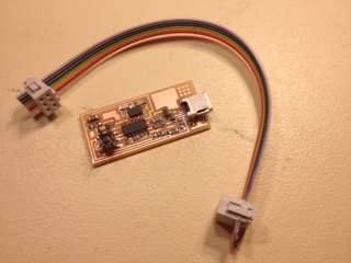
Here is the final product and the cable to connect it for programming. To make the cable cut a slice of ribbon wire and slide the open end of two female connectors over either end so their metal teeth will dig into each wire of the ribbon wire. Put the female connectors in a clamp and clamp down , now the teeth are connected to the wire and you have a nice header connection. The other cable you will need to operate this board is a USB to mini-USB cable to connect the board to your computer. The FabISP is used to communicate between your computer and another board, which we'll make in weeks to come.

After the board looked all good and dandy we plugged it in and were able to program it fine. You need another board to program this board, or you could use an AVRISP. Here is a nice tutorial explaining how to program the FabISP. My FabISP took the code in through the header pins and programmed without error, but when I turned it around and plugged the USB cable in the computer did not see my board. After some debugging it turned out that the mini USB port was not fully soldered and didn't make an electrical connection. I had also soldered the diodes backwards (the side closest to the line is the cathode). After re-soldering these the board worked!