EKG
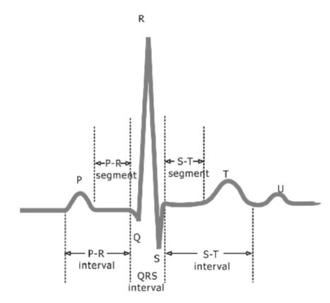
In 2.75 we did an EKG lab where I learned there is a small voltage difference across your chest of about 5mV caused by "the movement of ions through heart muscles." This difference can be used to sense your heart beating and the waveform can discern some useful medical data. Below is an image of a normal EKG waveform which is repeated each time your heart beats. I decided to use the data to drive an LED through a separate pin on the micro controller to flash to my heartbeat.
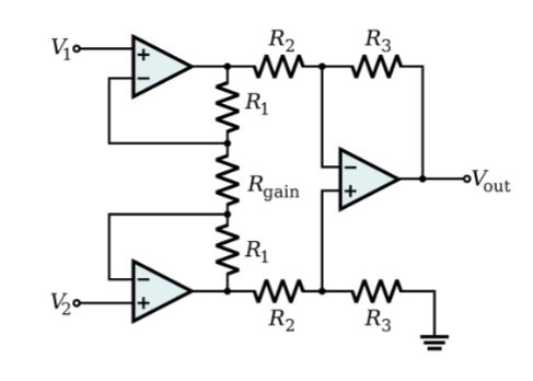
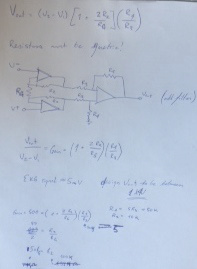
Magnifying this tiny but measurable voltage difference and feeding it into a micro-controller I can then send it to my computer. The ATtiny44 can produce a 20x gain, and it can read as low as 50uV so having an instrumentation amplifier really isn't necessary, but even with a 20x gain the signal will only be 0.1V so I added an instrumentation amplifier to make debugging easier. Because the FabLab was not stocked with instrumentation amplifiers I made my own from a series of 3 op-amps and resistors. The first two op-amps act to buffer the input signals and the third acts as a differential amplifier. I knew I wanted a gain of 500 because this would put the middle right at 2.5V, which is in the middle of my voltage rails (GND and +5V). I massaged the resistor values we had in stock to achieve the gain using the equation below. I added a low pass filter before feeding the signal into the micro-controller to eliminate some of the predicted higher frequency noise, particularly 60Hz from other electronics. Because our signal is our heartbeat, around 120bpm or 2Hz, I picked the R and C values to match a cut off frequency of 30Hz.
I made the circuit using Eagle. I started with my fixed programming board from week 5 and 7 and added the instrumentation amplifier having the output feed to a free pin on the ATTINY44. I removed the switch, but kept the LED so I can blink it to my heart rate. I also added 3 pads to connect to +V on the left side of my heart, -V on the right side, and ground which I can just grab.
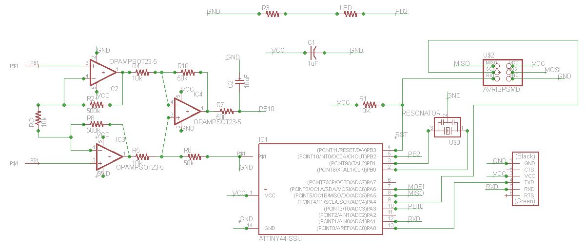
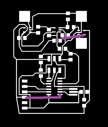
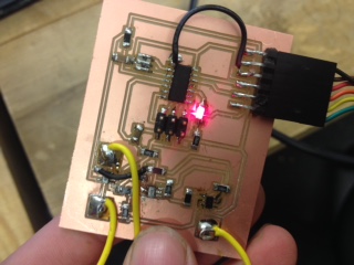
My first go around I did not connect the AtTiny44 to VCC again... It showed up in the schematic as connected, but when I went to the board view the connection disappeared and I didn't notice. This apparently happens if the netting is not snapped together, so you can add the green dots in the schematic view and move each part around to make sure everything is snapped together. Lesson learned, I will always check that the micro-controller is getting power from now on! I noticed this after cutting out the boards, so I just jumped a wire across to connect them. De-bugging I also found one of the op-amp wires didn't connect, so I also jumped that.
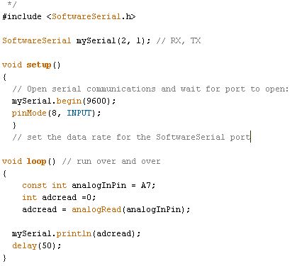
I bootloaded the ATTiny44 (internal 8MHz clock) with Arduino and programed the LED to blink. I had a lot of trouble getting this to work because my computer is having a rough time.
My computer forgot all the drivers, so though it used to recognize USBtinyISP she no longer does. Every time I came into work on it she acted differently. After I re-installed the USBtiny driver, tried with AVRISP, re-installed that driver, replaced the FTDI cable I bought on Amazon with an "official" version from digi-key... Looked at re-installing a FTDI driver, but Arduino automatically installs an FTDI driver. Nothing really consistently worked. I think one of the USB ports on my computer only provides power, I don't know why, but it does not consistently recognizing anything being plugged in and the device manager re-freshed every few second like it was having a seizure.
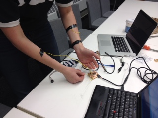
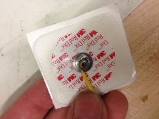
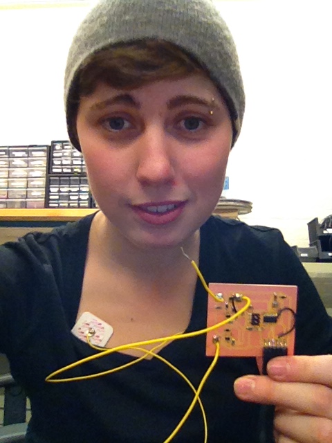
As I was fiddling with it I just had the ends of the wires taped to my arm because I was just looking for any signal. To get a nice, clean reading I took some EKG electrodes from the 2.75 lab and connected them to my circuit by soldering on wire. I then connected them onto me. I stuck them on either side of my heart following the guides for an Lead I ECG.
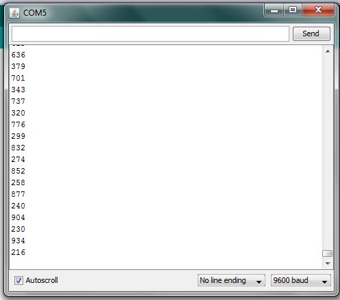
I compiled and uploaded the following code and with a lot of fiddling of cables and ports the serial port finally read something! I expected to work de-bugging the programming, not the connections. The values it read were centered around 500, which makes sense because I was expecting a voltage of around 2.5V. The analog-digital converter scales the voltage to a 10 bit number between 0 and 1024 for the serial post to read, and as 2.5/5~500/1024 I was happy enough to say I sensed something!