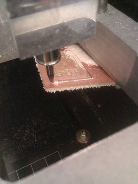
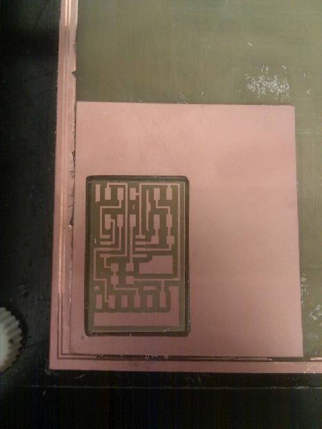
Milling out the example step response board.
I first made Neil's hello.load.45 step response board and used his code (C file, python file). Biggest issue that happened in this step: my board must not have been taped down well enough, because while milling it, the modela picked up the entire board. I saw it right as it was about to happen and stopped the machine, so no harm was done. I then soldered everything exactly as in Neil's design.
It works?!?! Sorry for the bad video quality guys.
For the first time ever, programming my board works on the first try!! I was seriously shocked by this. Maybe I'm gettting better at this? I also tried connecting the sense pin to a square of copper and touching that, instead of the pin directly, and it worked fine. I'm running Neil's example code here. I ran the make commands described here, then ran the python file on my Windows machine by running "hello.load.45.py COM5" in my command prompt (COM5 is the USB port my board was on. This can be found by looking at Device Manager.)
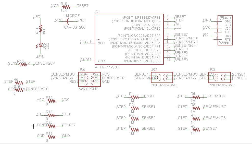
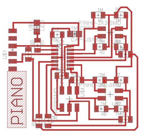
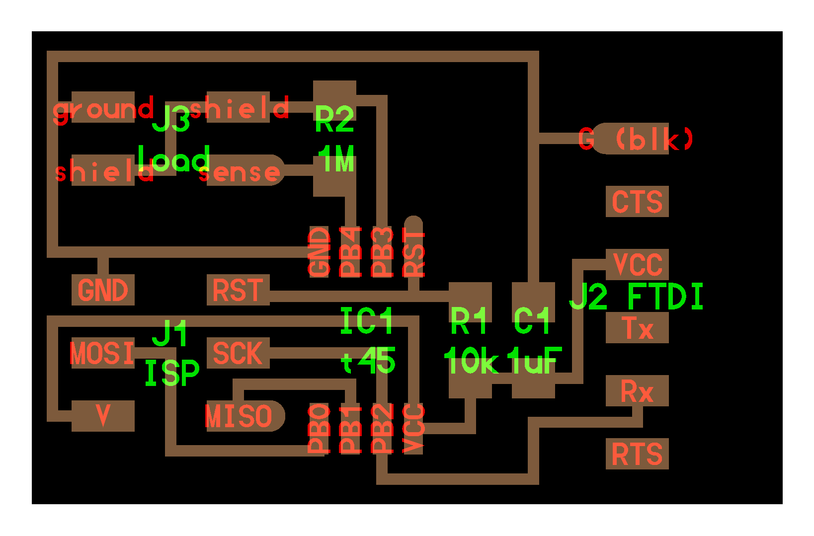
Designing in Eagle
With a lot of help from Prashant (thank you!), I was able to understand what Neil's board and code were doing, as well as design my own board. I also used ideas from Matt Blackshaw's design, as it also creates 8 sense pins (this is the most that can be used because the Analog to Digital Converter aka ADC only has 8 pins on the ATtiny44). Each 2x2 coupler has 4 sense pins, which will be connected to the keys by wires. I added an LED, since there were two unused pins on the ATtiny44 board. I'm thinking the LED can just light up everytime a key is touched. Routing was insanely difficult, and I ended up adding 8 0-ohm resistors to jump over wires. I've never added words to a board before, but figured with all of the (many) hours that had alread gone into this one, it warranted a name.
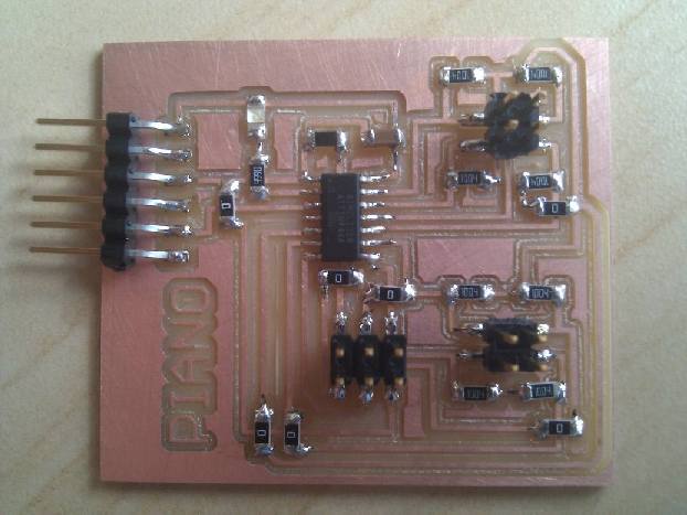
Making it
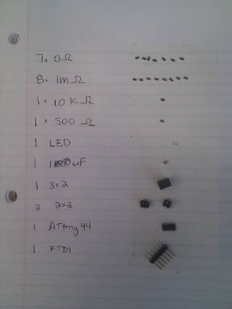
Got out all the components and soldered them on, double checking all of my connections by eye and with a multimeter.
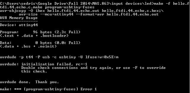
Of course.
I tried running my blinking LED code from the embedded programming week...and got a rc=-1 connection error. I went over all of my connections again, and checked that the board matched my design...but no luck. I ran out of time this week to do more debugging into this, but I was planning on using the board for both input and output devices. So I plan on figuring out what's going wrong, and add a sound output each time a key is pressed.