How does it work?
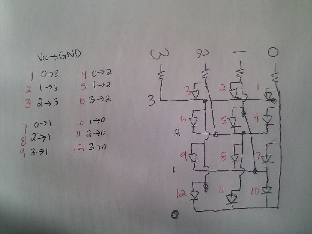
I drew out what I wanted my board connections to look like, just to make sure I had an understanding of how so many LEDs could turn on with so few pins. N pins can drive N^2-N LEDs -- or you could say N pins can drive 2*(N choose 2) LEDs. The second explanation seems more intuitive to me (and is seen in the drawing). Basically, since LEDs can only turn on with current going in one direction, you can use specific pins to only turn on one LED at a time. So from N pins, there are N choose 2 ways of picking a pair of pins. And each pair of pins can turn on 2 LEDs (by having current flow in one direction or the other). And since humans have such slow eyes, you can turn LEDs on/off so fast that it looks as if they're all on, even though you're just turning one on at a time.
Designing it.
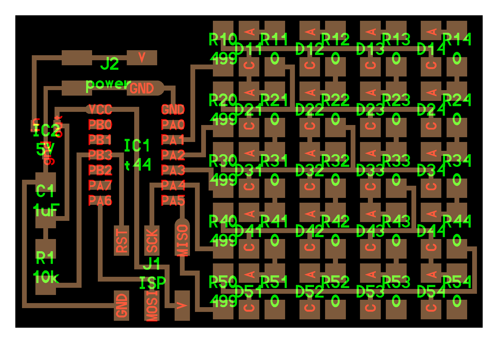
I tried to not have so many 0 Ohm resistors to jump wires...but still needed quite a few.
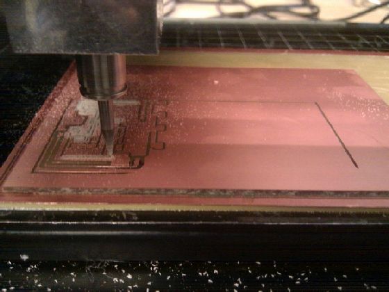
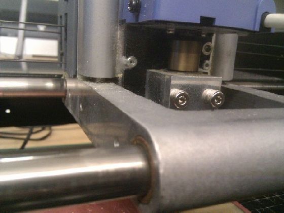
Modela problems
While milling it out, some parts ended up not even being cut out. I had to restart with a deeper cut, figuring my board must not just be level. Later on, while making the outline, the same thing happened -- the cuts just aren't going deep enough. Then I realize I haven't left enough space for the machine to move down that far (second image). I increase the space, and restart. Board comes out fine.
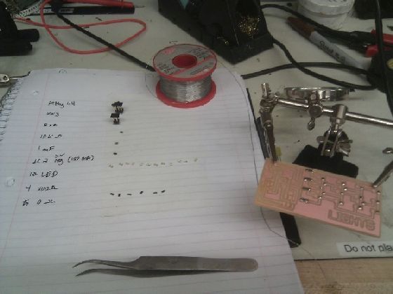
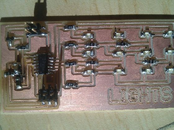
Making it
Got out all the components and soldered them on, double checking all of my connections by eye and with a multimeter.
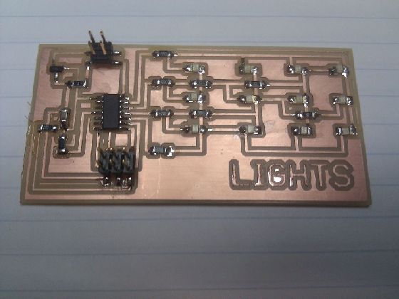
Errr, slightly burned
I try to run Neil's example code and get the rc=-1 error (of course). I've checked all of the connections, and don't get why it isn't working...so I decide to just remove the ATtiny44 and replace it. I do this with the heat gun, holding the piece by tweezers, and aiming the gun at the piece until the board drops from underneath it. I didn't even know it was possible to burn my board though, so guess I wasn't careful enough...the new ATtiny works though! The 2x2 header is being fed 7V (just need to make sure it's 5V or above, I think) from a power supply. I attached a 2x3 coupler on the header, since we didn't have any 2x2, and I stripped the wires corresponding to GND and VCC to connect them with alligator clips.
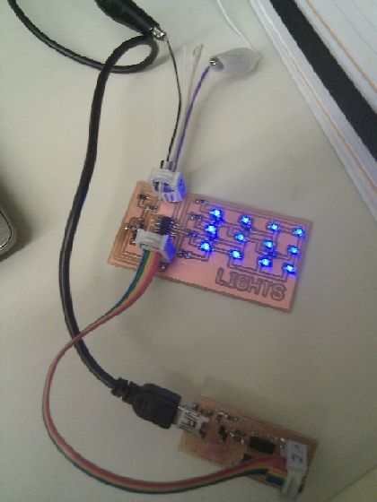
In action. With music.
This is running Neil's code, with the pins modified to match mine (PA0-PA3).