
Designs
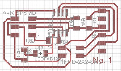
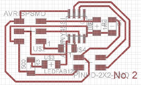
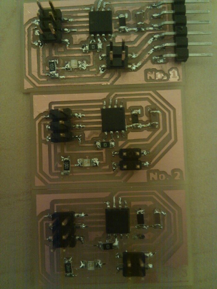
I remade Neil's wired network boards, adding an identifying number to the corner of each board (they're labelled 1, 2 , and 3). Board 1 is the only one with an FTDI cable, and provides the power to go to all other boards. Boards 2 and 3 are identical. The boards are then connected using the 4 pin header, which shares power, ground, Tx, and Rx. When programmed, the boards will have these identifying numbers saved.
Modela problems
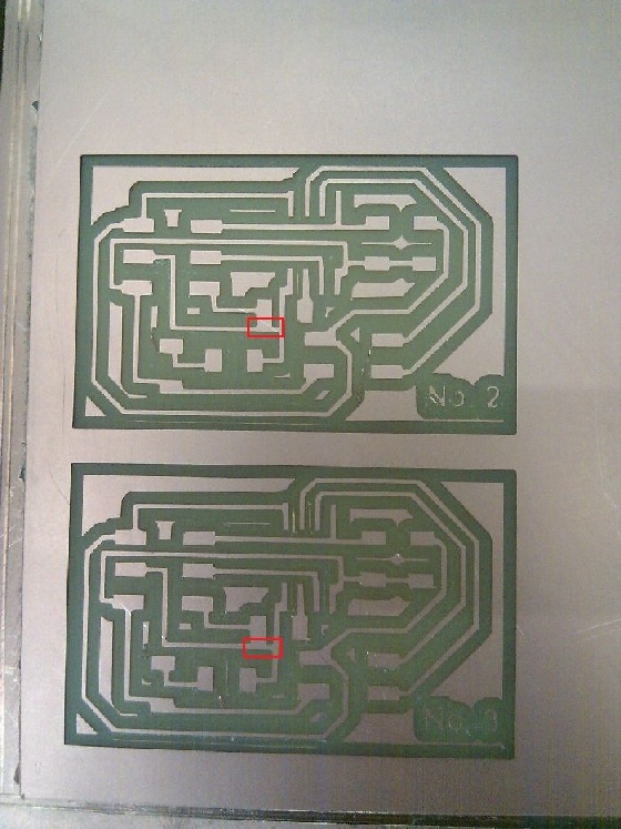
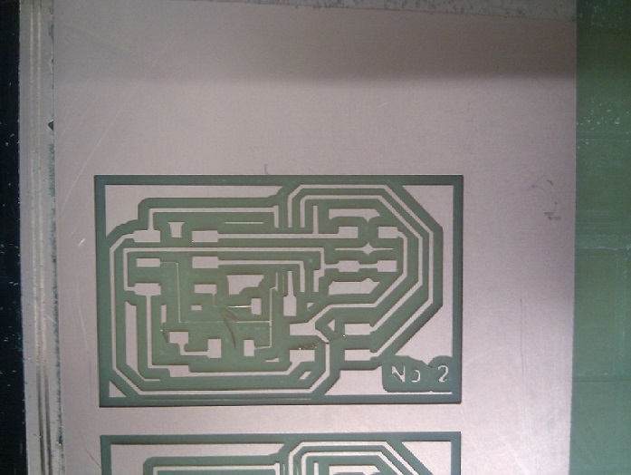
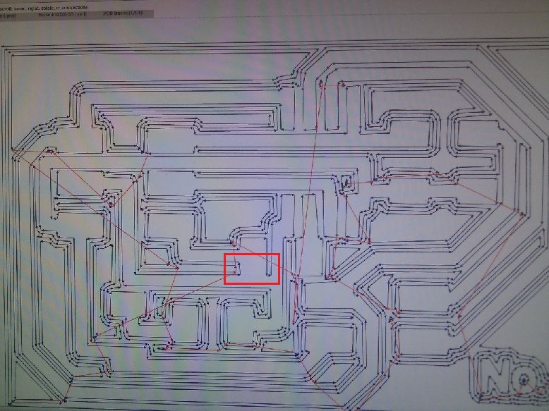
You'd think I would have gotten used to the modela by now and be a pro...nope. I didn't notice before milling that one trace wasn't fully cut out (boxed in red). I tried to salvage this by rerunning the modela on just two of the traces. I should have changed the settings on the machine though, and only told it to do one outline (instead of the default 4). So in trying to fix board #2, I accidentally destroyed it, along with my board #1 (not pictured).

Hacky Fix
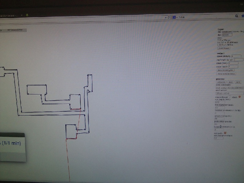
The fabmodules wouldn't cut though the trace unless I lowered the tool diameter from .4 mm (what it really is), to .1 mm. This seemed a bit too drastic to me, and I didn't want to destroy any more boards, so I instead recut out my boards with the default settings on the original trace file. I then just uploaded an image of one trace, and did one outline of it (telling the fab module that the tool diameter was small enough to fit). This worked just fine.
Milled and stuffed
The milled out numbers don't look too great, but I didn't feel like fixing them. I should have made them bolder, so the cut outs wouldn't be so thin (for example, the 'No. 3' has almost come off). Only one out of three boards didn't work when connected to the computer! After going over all the connections another time, I had three out of three working. Score.
In action
This is running Neil's code, with the node ids modified to match mine (1, 2, and 3). To program boards 2 and 3, I connected board #1 to the computer using the FTDI cable, connected the chosen board (2 or 3) to board 1 using the 2x2 header, and connected the chosen board to my ISP programmer using the 3x3 header. The node id is changed in the code for each board, but everything else remains the same.