Floating House, Seattle.
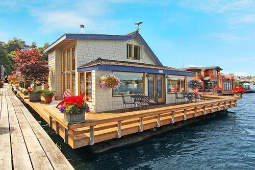
Floating House, Seattle.
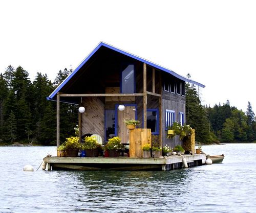
Floating House.
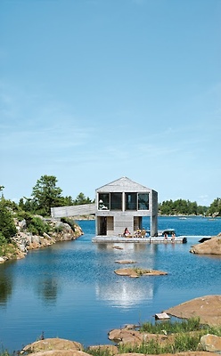
Floating House
Step 2: Stuffing the Board
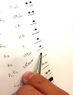
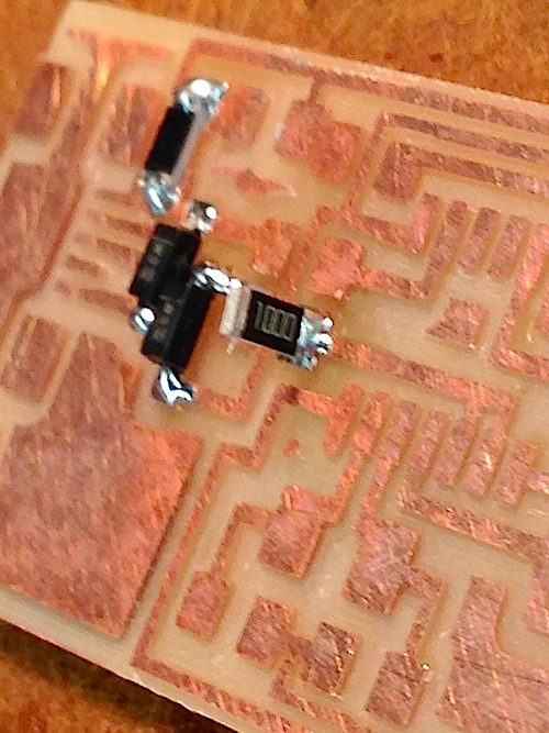
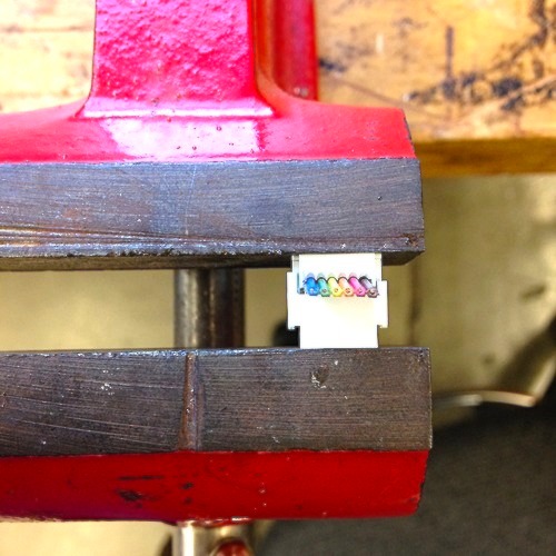
Once the traces were milled, we shop-vac'ed the board clean and gently abraded the surface with ultra-light sand paper to remove any copper burrs. Next we collected all of the tiny components we'd need to "stuff" (solder bits to) the board. Dealing with microscopic, unfamiliar, and sometimes unlabeled bits in a configuration whose sense was still mysterious, it was super helpful for orientation and workflow to: 1) list all components: (resistors, capacitors, oscillator, microcontroller etc.), 2) lay down a strip of double-sided tape alongside list, 3) collect components with tweezers and place beside names.
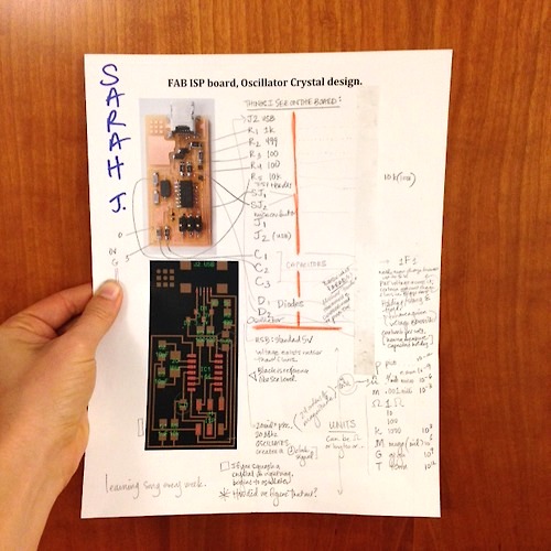
Worksheet Printout w/ Sticky Tape