Week 5: Electronics Design

Adventures in Making

What is Electricity?

__

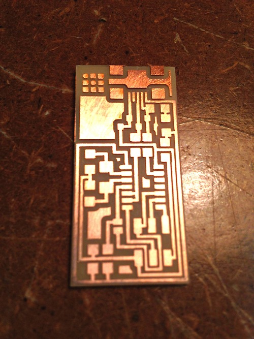
This week's new tool was the Modela MDX-20 Milling Machine. The Modela kind of looks like a printer, but it's stockier and sturdier and is equipped with a drill bit instead of ink. While a printer adds material, the Modela works by subtracting away. Here it is at work. Our task was to mill a small rectangle of FR1 phreonilic paper (thin layer of copper over plastic-reenforced wood fibre) to create the base of the our Fab In-System Programmer. The milling machine "prints" by using different sized endmills (tiny drillbits) to subtract the top layer of copper, leaving a network of narrow traces like this (see below). To mill the intricate traces we used a 1/64" endmill and for cutting the board out we used the heftier 1/32" bit.


Project 01
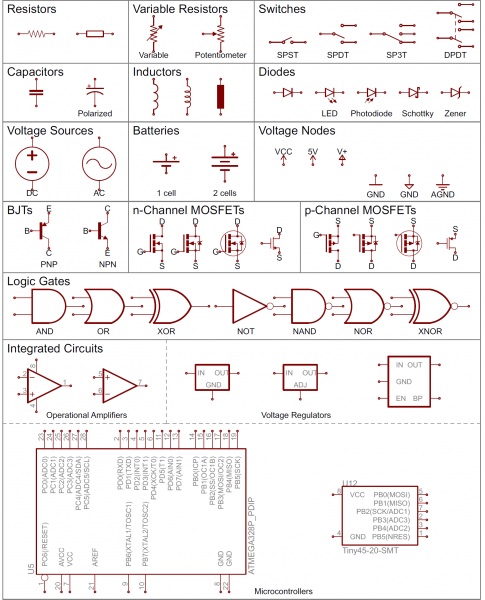
How do I read this thing? Schematic from sparkfun tutorials
Project 01a
Milled traces for the FabISP


Step 2: Stuffing the Board

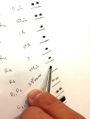
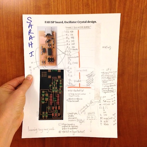
Once the traces were milled, we shop-vac'ed the board clean and gently abraded the surface with ultra-light sand paper to remove any copper burrs. Next we collected all of the tiny components we'd need to "stuff" (solder bits to) the board. Dealing with microscopic, unfamiliar, and sometimes unlabeled bits in a configuration whose sense was still mysterious, it was super helpful for orientation and workflow to: 1) list all components: (resistors, capacitors, oscillator, microcontroller etc.), 2) lay down a strip of double-sided tape alongside list, 3) collect components with tweezers and place beside names.
Project 01b2
Worksheet Printout w/ Sticky Tape
Project 01b
Collecting Bits on Double-Sided Tape

What We Learned

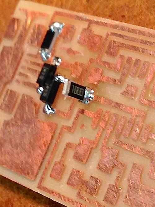
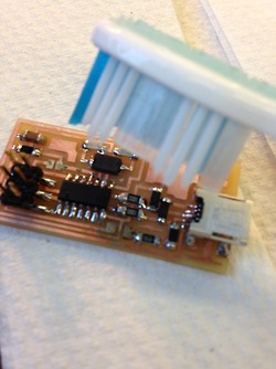
a) Heating up the copper square (pad) beneath the piece you're about to solder is helpful to prime the flow. b) 1-1-thousand, 2-1-thousand, 3-1-thousand, 4-1-thousand is usually how long it took for the solder to melt when we used copper braid to wick the solder back up off the board. c) it's possible to accidently solder a piece vertically in the air (see photo). d) Flux looks like marmite. It's messy, but it works to help stubborn solder become mercurial again and wick up like liquid. e) soldering under a x7 power microscope is actually remarkably easy and satisfying. f) In the milling stage, think of x-min, y-min as the southwest (bottom left) corner of where you'd like the Modella to start milling. g) their are several parts that have directionality (they need to be in a certain orientation to work): 1) Diodes (D1, D2) have an anode (A) and cathode (C) end. Look for the tiny line that marks the cathode end. 2) Microcontroller (looks like piece of centipede) has a tiny dot that needs to be oriented to line up with R3 (upper left when hold board w/ USB on top).

Project 01
Soldering Resister on its Head Oops
Project 01a
Flux to Flow the Solder
Project 01a
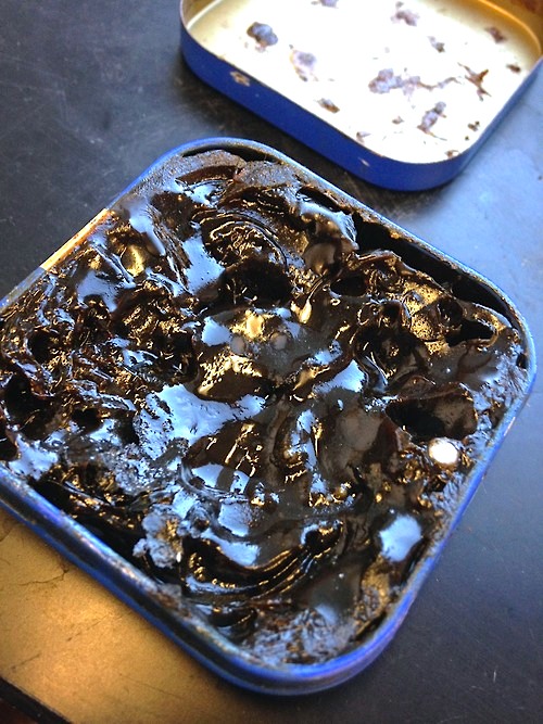
Not Marmite

Programming the Board

...

Project 01a
Golden Gate Wire
Project 01a
Though counterintuitive, good to brush clean board w/ soap and water.
Project 01a
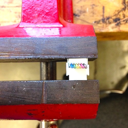
Clamping Plastic Socket w/ Header Pins onto Rainbow Ribon Cable

Rob H. suggested that we clamp the wires together with a vice until the gap on the sides of the white plastic closed. Make sure that the ribbon cable is centered under the pins before clamping socket. Be sure to clamp evenly; clamp once, flip socket 180 and clamp again to ensure even closure. Header pins are biting through the colored insulation to touch the conductable wire inside. If socket clamps unevenly, might short the wires in the ribbon cable. If you don't have a vice, try tap, tapping with the hammer. This Instructables Tutorial cautions against using wires because it's so easy to clamp sideways and mess up the connections.