Week 5: Electronics Design
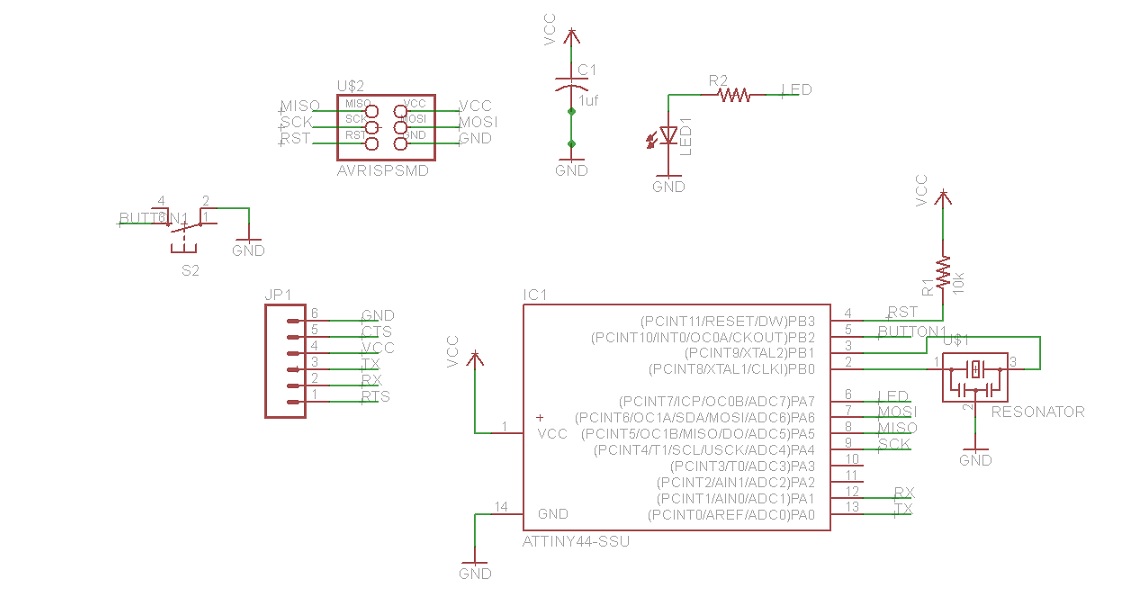
This week, I designed a basic board using Eagle and
fab.lbr. The first step is to create a schematic. The finished
product is as below.
My key learning:
- Eagle works differently from other design software that I've
used. You need to select the function first before you select
the object that you are applying the function to.
- Useful commands: value, name, move, group.
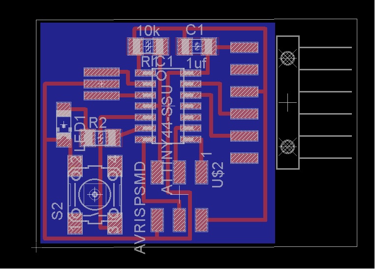
After designing the schematic, switch to the board. Eagle provided
me with a half designed board. I used "route" function to connect
the parts. Since the parts do not fit into the automatically
generated board. I used "group" and "move group" commands to change
the arrangement and space on the board so that all parts can fit
well. Wires cannot cross each other, but you can put a wire under a
resistor when necessary.
Finished product is as follows:
After the design work is done, we need to check the output against
design principles. I used DRC command and then the "clearance" tab.
As Eagle responds with "no error" message, I started the export
process.
For export, I first used "layer" command to display only top and
dimensions, with "monogram, 500 dpi, png format" as my requirements.
Then I exported the bottom rectangular as the frame for the cut out.
Afterwards, we can load the files into the fab module and make the
board!