The assignment this week was to make a FabISP in-circuit programmer for use in future projects. This assignment incoporated the following skills: using the fab module, creating a PCB on the Roland Modela CNC mill, and soldering electrical components into place.
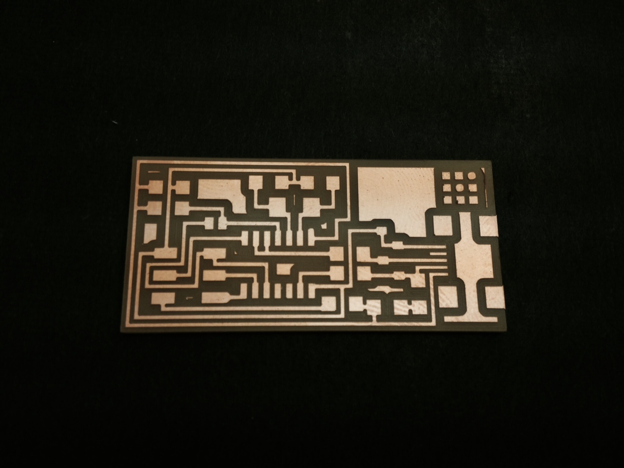
I first loaded the standard image file for the PCB traces that was stored on the lab computer into the fab module. I followed the tutorial provided on the class webpage and used all the default settings (indcluding using a cut depth of .1 mm and 4 passes). With a 1/64 end mill, I cut the traces but found that some portions of the board were not cut all the way through. Copper was still left between traces in one corner of the board. This was probably due to my part not being completely flat. Without removing the part, I changed the cut depth to .15 mm and ran the path again. This time it cut all the way through. I then switched to a 1/32 end mill and mill around the border using the image for the PCB outline. I used all default settings and it worked fine.
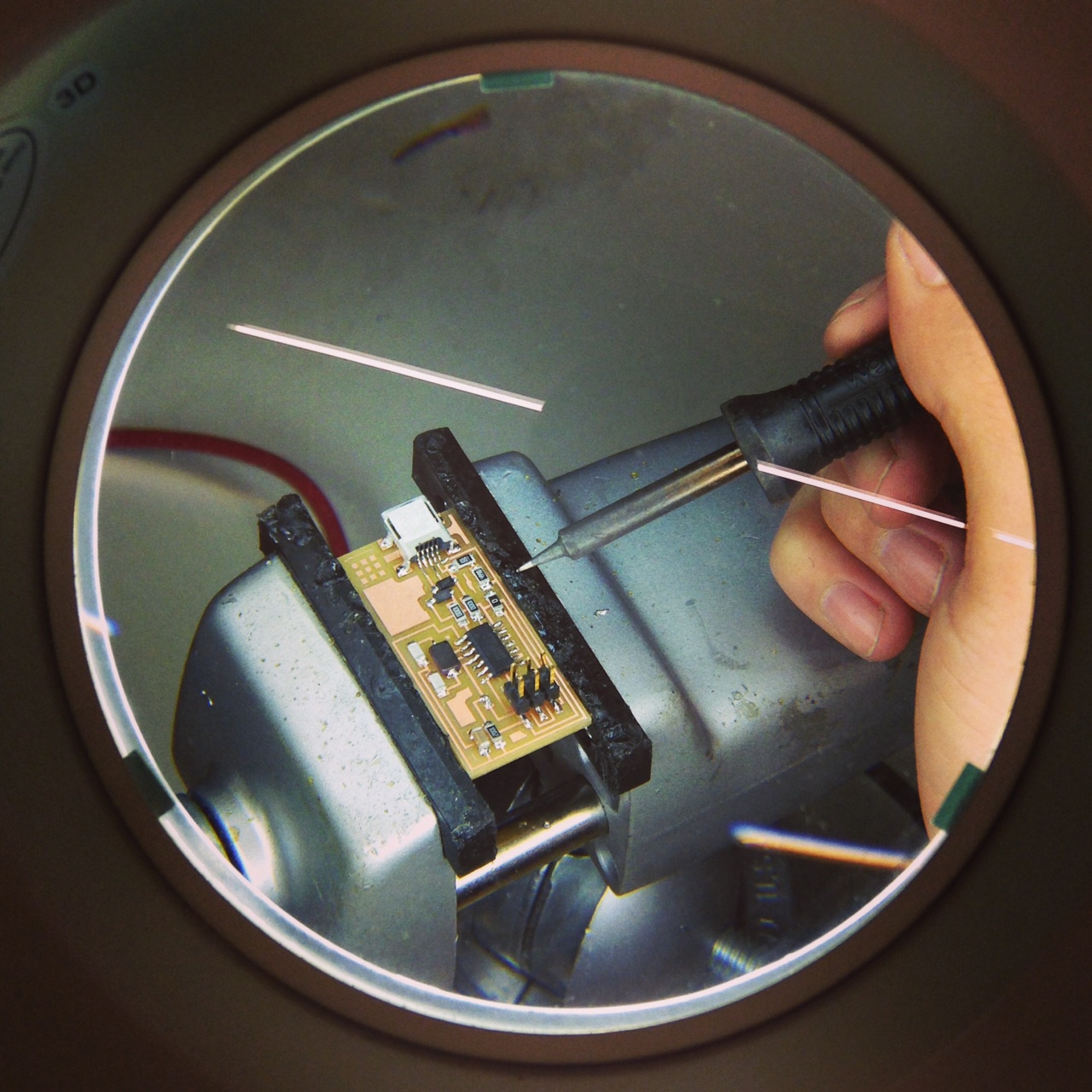
Next, I took the PCB to the soldering station and began to attach components. I followed the diagram and the picture of the completed PCB provided on the class webpage. I used Rosin flux which I spread over the board with a paper towel and set the iron to 720 deg. According to Jean-Francois' advice, I started with smaller, "closer-to-the-board" components and worked my way outward to the larger components. This helps avoid the problem of bulky compenents blocking access to the board with the tweezers or iron.
With all the components in place, I liberally applied a flux remover, rinsed the programmer in the sink, and the project was complete.
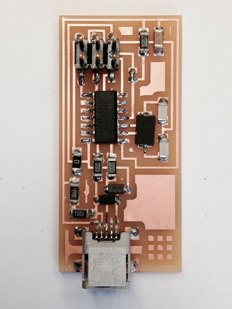
One difficult part was identifying the correct components to use. I either had to trust that every component was shelved properly and the labels on the cubbies were correct, or I had to learn how to identify the components by their markings. I'm not a very trusting person. I was confused for a moment by notation of the resistors and what size resistors R3 and R4 were supposed to be. The diagram of the programmer says 100 and the picture shows resistors with markings "100R" but the resistors in the 100 Ohm cubbie said "1000".
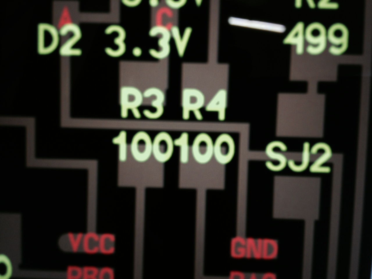
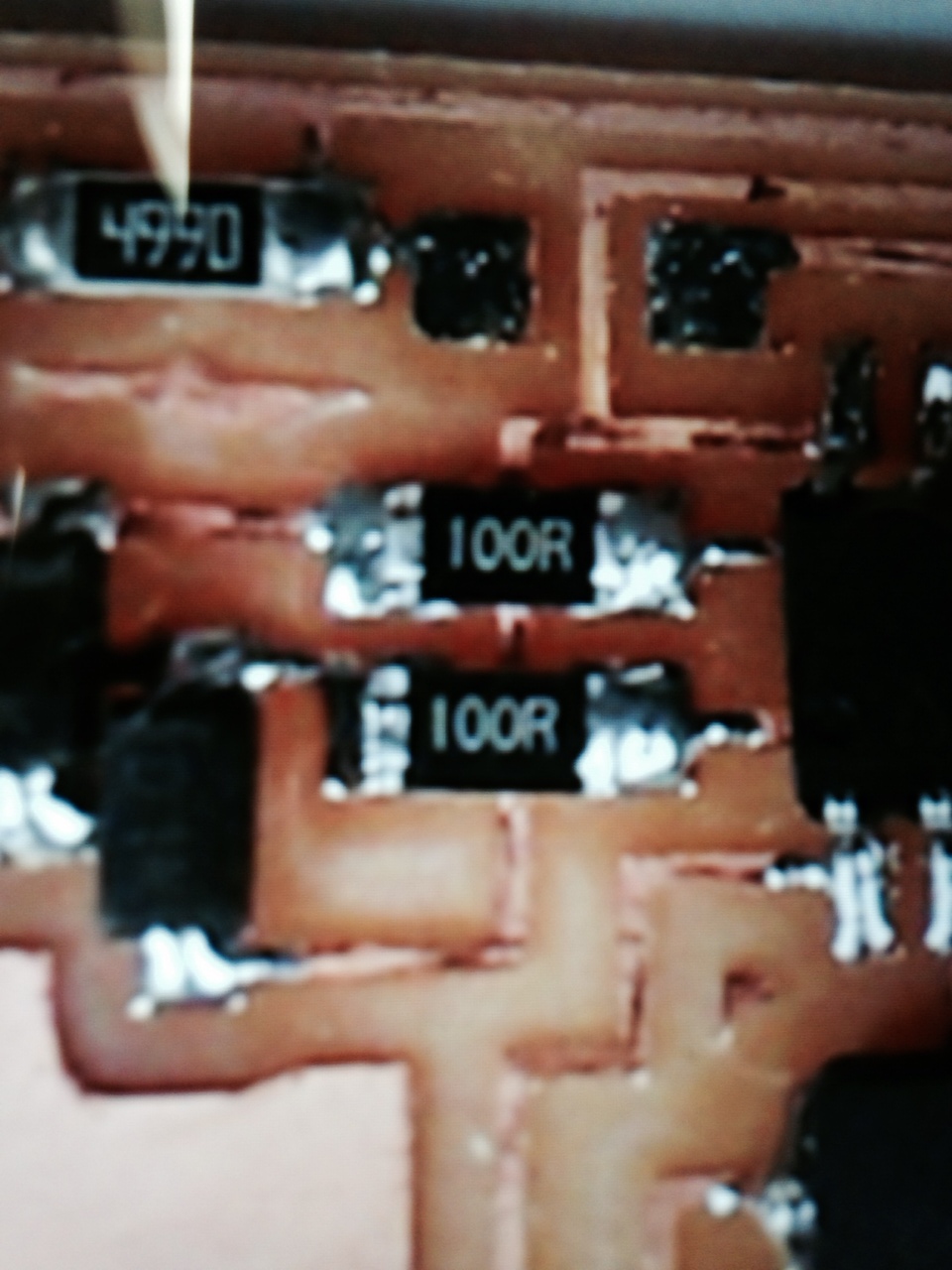
I then found resistors that said "R100" in the cubbie for .1 Ohm resistors and I wondered if "R100" was the same as "100R". After searching on the internet, I found I was being confused by the use of two different kinds of notation. I eventually figured out that "100R" means "100.", that the R represents the placement of a decimal. So "R100" is ".100" or .1 Ohm and is not the same as "100R". In the other notation "1000" means "100*10^0" or 100 Ohms (equivalent to "100R") and this was the resistor that I wanted to use. Other than that little hang-up and having to mill the board twice, the process was pretty seamless.
Home