This week I finished off my final project which is a speedometer for my longboard. It worked out pretty well -- I got it working and telling my speed and everything came together, but there was some bonus functionality (adding a calibration mode) that didn't work out. Below I will talk about each product of the process in the context of a skill learned in the class
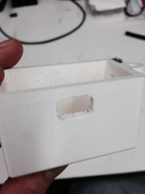
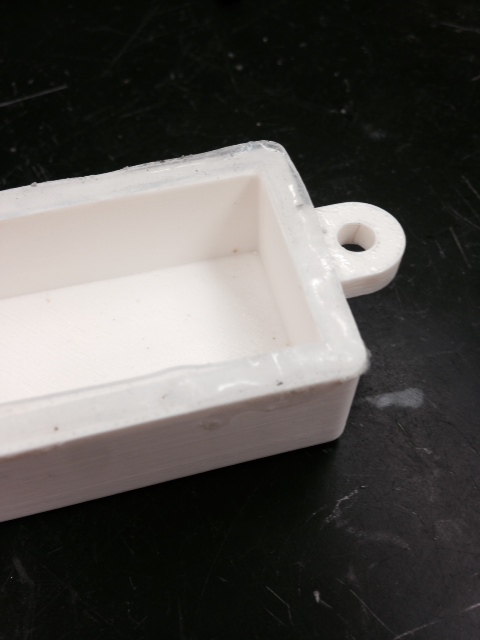
I 3D printed a couple of enclosures to house the electronics. I drew the parts in SolidWorks (including slots to let cables in and out), exported as STLs to a proprietary 3D print software (Insight) for orienting and slicing, and then sent to Fortus printer in my lab. It took about 6 hours to print and then a couple of hours to dissolve the support material. The parts came out very nice.

Then I realized that I hadn't included a hole for a power switch so I hand-drilled a hole and widened it out using a file.
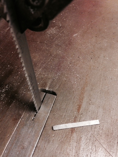
Also, unrelated to 3D printing but a misc. piece of the process, I used a band saw to cut a thin piece of sheet metal which I bent into an L and used to secure the hall effect sensor (see Inputs week) to the truck of my longboard.
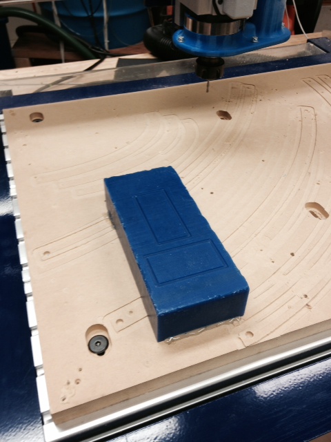
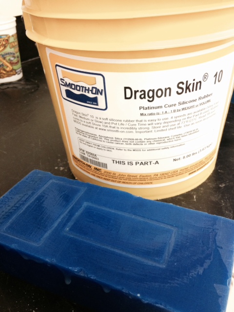
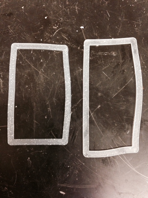
Next I created some custom seals using casting techniques. The board has a little bit of curvature so I wanted something to put between the electronics enclosures and the board to fill in the gap. Also, I sometimes go through puddles and I don't want the electronics to get wet. To do this, I drew the parts in SolidWorks, exported to VCarve, used the Shopbot to cut the molds out of machinable wax, filled the molds with Dragon Skin 10 (only takes 10 minutes to cure!), and scraped off the excess using a popsicle stick. Once the pieces had set, I peeled them out of the mold and used cyanoacryllate to glue them to the electronics enclosures.
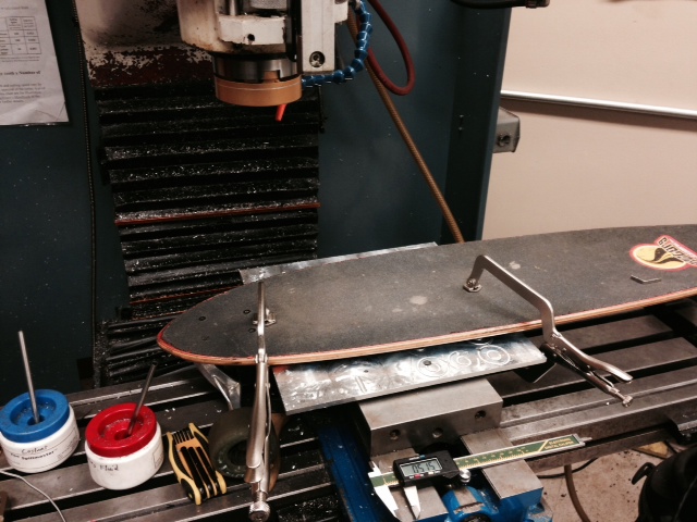
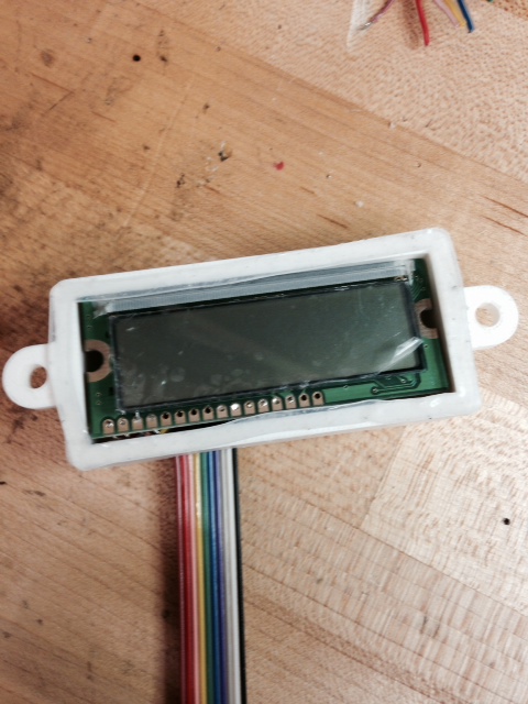
Next I cut a hole in the deck of my board for mounting the LCD. I used the mill to cut a through pocket and a slightly larger partial depth pocket for fitting an acryllic screen.
I created the screen to cover the pocket (protect the front of the LCD) on the laser cutter. I drew the screen in SolidWorks, sent to CorelDraw for some processing, then sent to the Epilog laser. I cut the piece out of 1/8" acryllic. It fit on the first try!
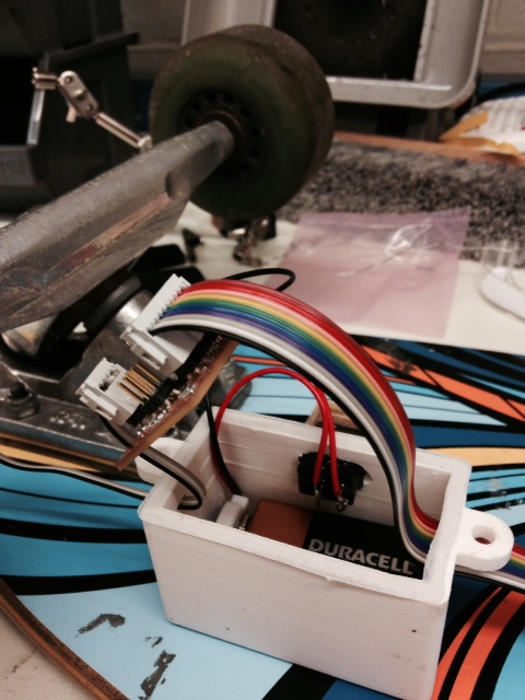
Most of the electronics I did in previous weeks (see Outputs weeks), but I did spend a considerable amount of time trying to add in a new component for a calibration cycle. First, though, I fit the components into the enclosures (LCD in one box; 9V battery and circuit in other box). I had to thread the wires through the holes in the enclosures and then attach the connectors. This worked pretty well and wasn't too difficult. I left myself just enough room in the enclosures to maneuver the parts a little without wasting a lot of space.

I wanted to create a calibration cycle so that the same code would work with any size wheel (note: the code works by counting revolutions in a specified period so it needs to know the distance -- circumference -- associated with each revolution). To do this, I included a button on the the outside of the enclosure which a user could press to initiate calibration. The screen would then indicate that they should input the diameter of their wheel which they could do by spinning the wheel to cause a counter to go up until they reach the correct number. They would then push the button again to end calibration. I got all of this programmed in arduino (see code here) but it turns out the Attiny 44 doesn't have enough memory to handle it and we were out of 84s. Anyway, I was also trying to not remake the board but use the one that I created a couple of weeks ago. To do this but add in a new button, I created a very special connector pictured below. This connector snaps onto the ISP header (after programming). There is a jumper from the VCC header to the MOSI header (which connects to an unused pin on the MC) with a 100k Ohm resistor in the middle. The MOSI header is also wired to one side of the button and the other side of the button comes back to the GND header. This makes the pin pulled HIGH when the button is not pushed and LOW when the button is pushed. It worked pretty well and was a very efficient use of space.
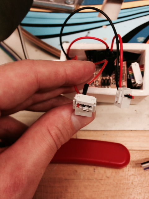
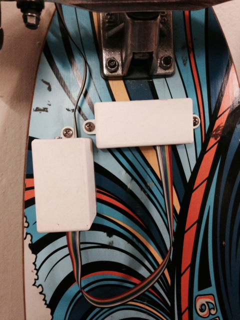
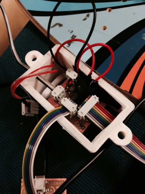
Below I have some pictures of the electronics in various stages of assembly. One notable thing that I tried to do is make all of the external pieces connect using headers so they could be removed to be able to pull the board out for troubleshooting (turned out to be a very good idea) and access the battery for changing. Notice all of the connectors in the following picutes

In the end it worked pretty well except for the calibration cycle not being feasible because of a lack of memory. I attached the enclosures to the bottom of the board using 8-32 screws (pre-drilled undersized holes and then threaded them in by force) and the seals worked really well. Feels very solid. Then I took it for a spin and it works! Future work includes getting a bigger MC to be able to use the calibration cycle and upgrading the LCD (something back lit and maybe something with bigger numbers -- 2 digit display).