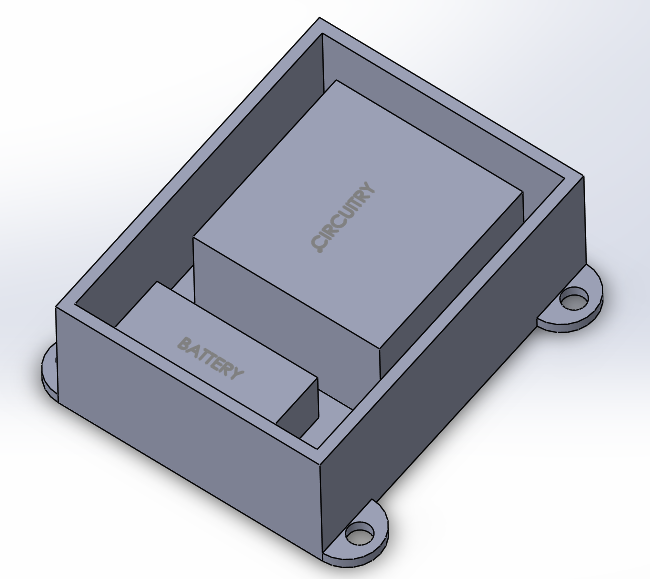
For my final project, I would like to make a speedometer for my longboard. The basic architecture of the speedometer is a probe (inductor) near the inside of the wheel to detect a magnet each time the wheel makes a revolution. This input will go to a circuit (that as of right now I have no idea how to design) which will interpret the signal and output the speed of the longboard to a display mounted on the deck. The circuit and a power source (battery) will be housed inside a protective box which will be mounted on the bottom of the deck.
Below, I have some models of the system that I made in Solidworks. As you can see, I spent a lot of time making the models and not so much time on the rendering. I will make better renders at a later time. I decided to model the board even though I won't actually be making a board since it's important to be aware of certain important dimensions (e.g. the height of the board for clearance of the speedometer housing). Also, I just wanted the practice in Solidworks. The picutures show four parts: the control box, control box lid, probe (near the front, wheel), and the display.


I think this project will incorporate several fabrication process. The circuitry will probably require making a PCB. I will have to solder some components like the leads to the probe. The box may be made using milling operations (if metal) or potentially 3D printing, laser cutting, or CNC routing (TBD). I haven't figured out how I will attach the probe to the trucks of the board (or if it will have some kind of housing -- right now it's just a generic shape floating over the trucks), but I could create a stretchy, rubber strap to go around it.
There is plenty of design work still to be done, but I think there is lots of potential here to put to use the skills I gain in this class. Plus it's something I've always wanted to make!
Home