This week's assignment was to create and program a new board with an input device. I created the first piece of my final project which is the main circuit board of my longboard speedometer. I used a hall effect sensor as my input device and an LED to use as an indicator (since the board does not have serial communication to the computer). I also added connections for an LCD screen which I will use next week because I know that I'm going to want to be able to output the speed to a screen.
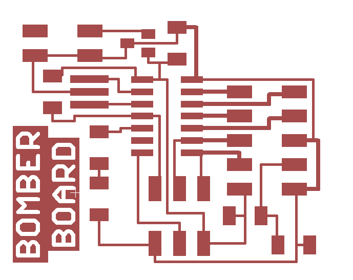
I used Eagle to design the board (see previous weeks' examples). I knew that I would need to use an ATtiny 44A because the LCD screen requires 6 output pins from the microcontroller and the hall effect sensor and LED each require a pin. This rules out the possibility of using a smaller controller with less pins. For the hall effect sensor, I chose a pin on the ATtiny that could be used as an ADC and as an interrupt becuase I'm not too sure yet which way my final program will use the sensor. See below for schematic and traces.
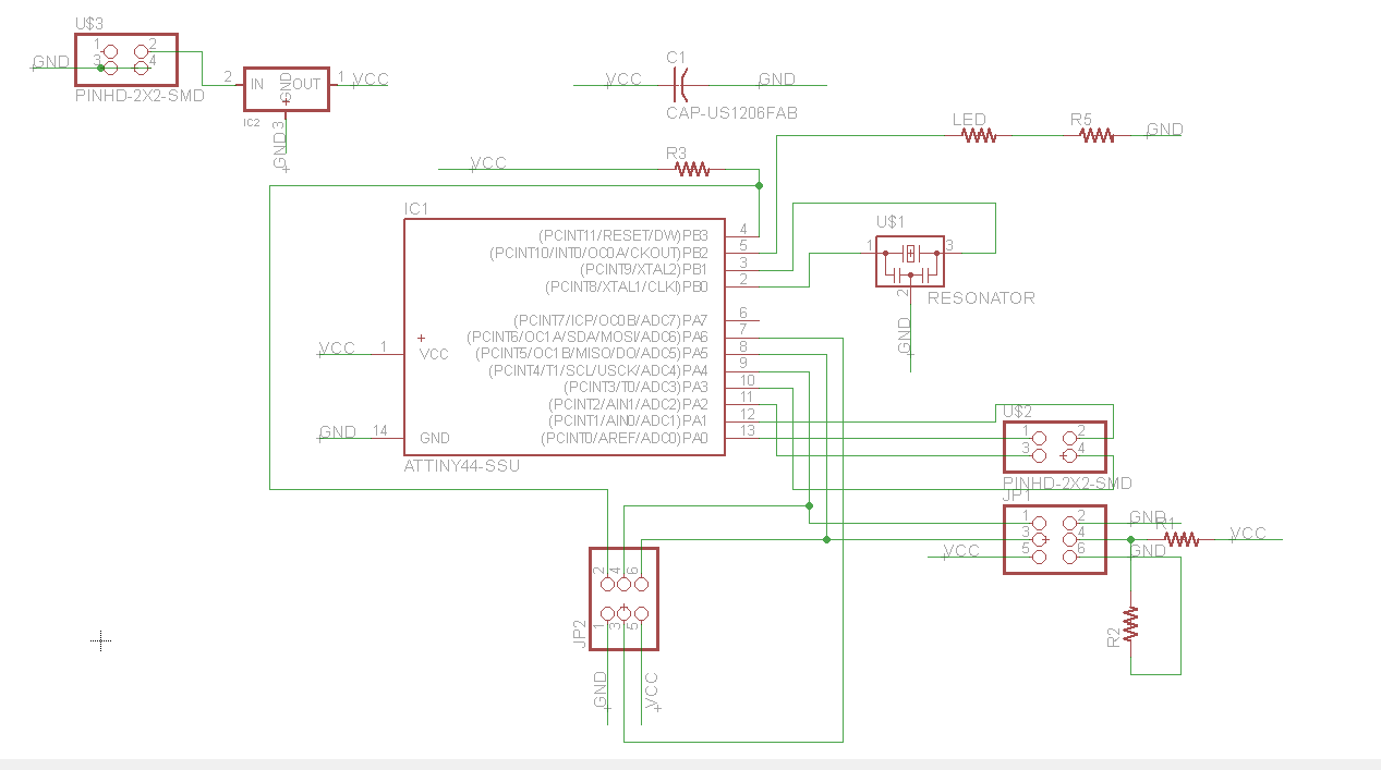
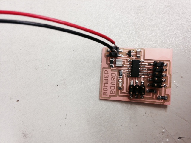
Next I fabricated the board using the same processes described in detail in previous weeks (Modela, soldering, etc). Since this board is not connected to the computer, it has to have a separate power source so I attached a connector for a 9 Volt battery. Note: As can be seen on the schematic, the 9 volt power supply has to travel through a 5 V 100mA regulator before it becomes VCC. This ensures that the microcontroller, hall effect sensor, and LCD get a steady and tolerable level of power. Also, I decided to attach the hall effect sensor using wires so that it could be located remotely from the circuit. I attached the leads directly to the MC, though in hindsight, I think it would have been cleaner to give the leads their own pads that were tied into the rest of the circuit through traces.

As in previous weeks, I used Arduino IDE to program my board. For a detailed description of how to set up Arduino IDE to work with ATtiny and the FabISP, see my page on Embedded Programming. This week, I first wrote some code to just turn the LED on when a magnet came near the sensor. This was pretty straightforward. Just use analogRead(pin) and an if statement to turn the LED on if the sensor is above a certain value. Note: the sensor outputs 2.5 V if no magnets are near and then lowers to 0 or raises to 5 depending on th e polarity of a nearby magnet. Also note that analogRead() will output a value between 0 and 1023 which must be determined using the data sheet of the microcontroller. Since this pin has a range of 5V, a reading of 2.5V corresponds to about 512 from the analogRead() function. After verifying that this works, I wrote a more complicated code that will be more similar to what I will do for the final speedometer. I'm sure there is a better way to do this (e.g. hardware rather than software) but my sampling rate is pretty low so this should be fine for now. Basically what I have done is specified a time interval over which the MC should count the number of times that a magnet passes near the sensor. With the magnet attached to the wheel of the longboard and the sensor mounted nearby, this will be used with some simple arithmetic to translate rpms to mph. In this code, I tell the LED to quickly blink 3 times to signal the beginning of a sampling interval. I then pass the magnet by the sensor a certain number of times. When the interval has ended, the MC shows that it has counted the correct number of passes by causing the LED to long blink that same number of times. Then it starts over. See the code and a demonstration below..
