This week's assignment was to design and build a network that uses at least two microcontrollers. I built a really simple network this week that simply allows me to push a button on one board and cause on LED on another board to light up. Although it was simple, I really solidified my understanding of electronics design as I built the circuit completely from scratch, used an MC that I hadn't programmed before (which makes me do things a little differently in Arduino IDE), and had to overcome some obstacles to power two boards from one source when certain programming pins are also used as network communication pins.
I used Eagle to design two boards (a master and a slave). The two boards were pretty similar except that the master has a header to attach a 9V power source, a regulator, and a button, and the slave has an LED. Because they are so similar, I was able to make the circuit for the slave for quickly after making the circuit for the master. I simply saved the master circuit under a different name, changed a few components in the schematic, and ripped up and relayed a few traces. I was surprised by how seamless it was. The two boards are pretty simple. They include the resistor and capacitor to make the MC function properly, an external resonator (in case I want to do some more stuff with precise timing later on), a header for the ISP, and a header to pass 5V, ground, and two communication pins between them.
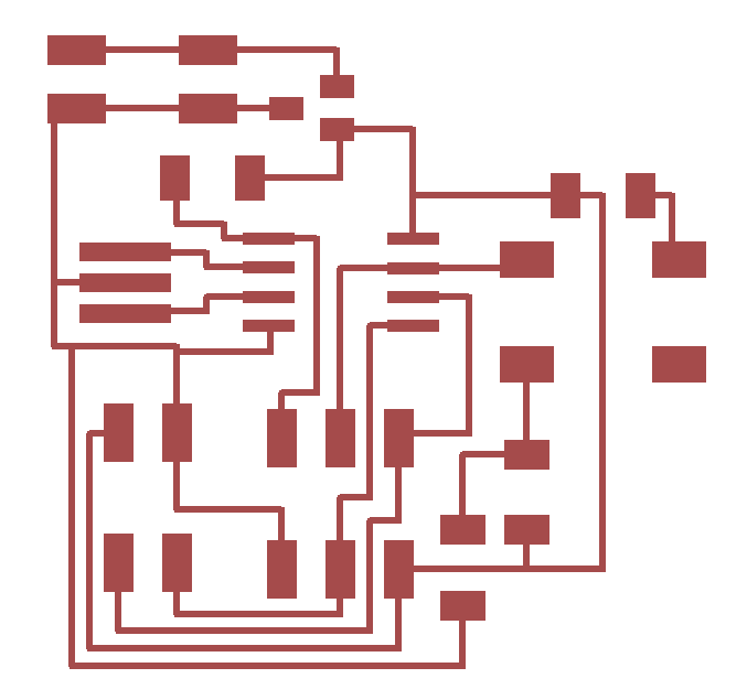

The code for these two boards is also very simple. Through the header, I connected Pins 1 and 0 of each board. I programmed the master board to have Pin 1 as an input (from the slave -- in case I want to do more complicated things in the future where the slave needs to communicate back to the master) and Pin 0 as an output, and I did the opposite to the slave. Then I simply to the master to turn Pin 0 on when the button is pushed, and I tell the slave to turn the LED on when Pin 0 goes high. The only tricky thing about this whole process was actually getting the programs onto the boards. For the master, it was pretty straightforward. I connected it to the FabISP and to its external power source like I have done in previous weeks on other boards
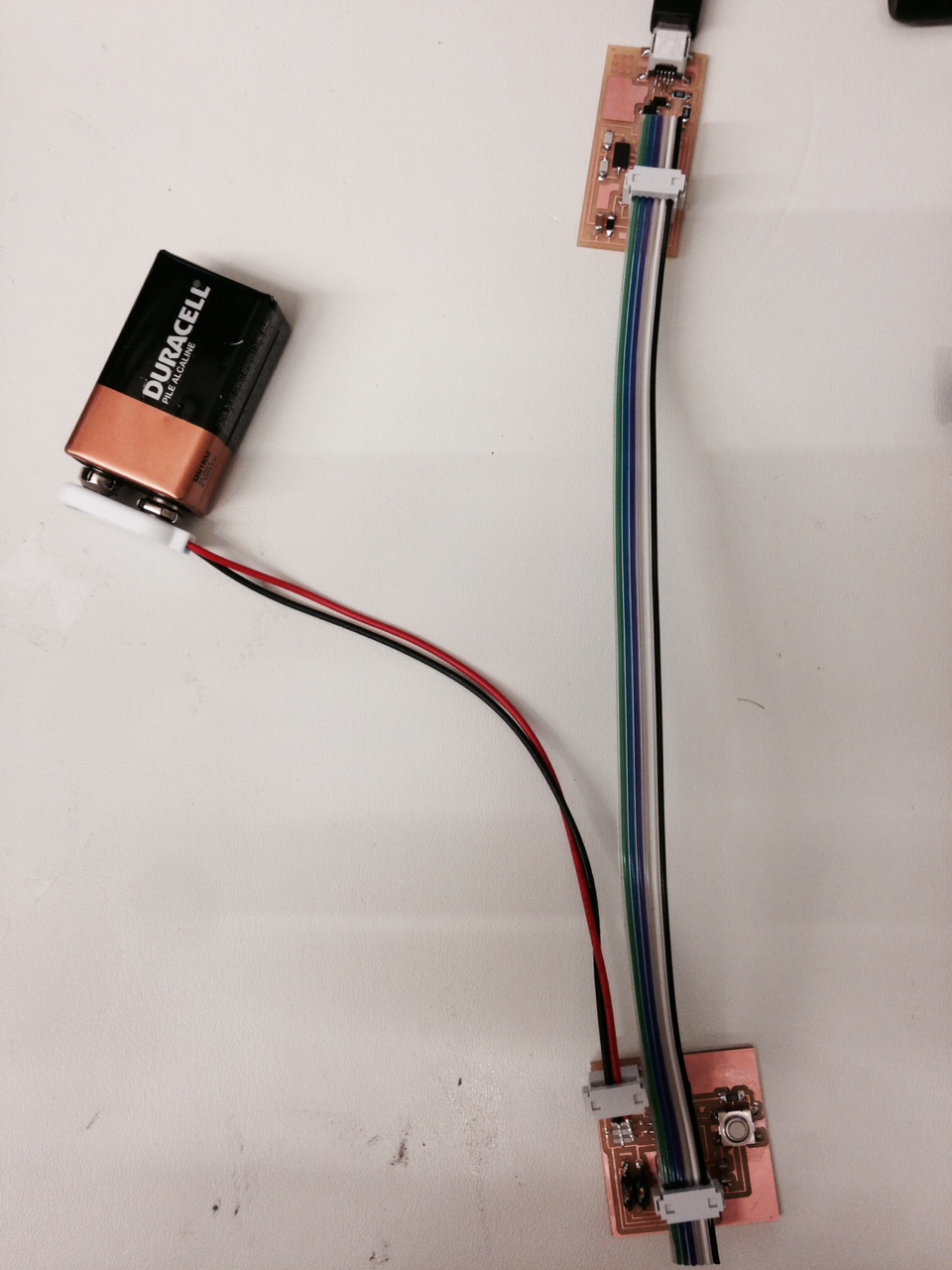
For the slave it was a little more difficult. I had to power the board in order to program it which means it needed to be connected to the master (which has the power source), but the header that includes VCC and ground also includes Pins 1 and 0 which are the MISO and MOSI pins. In order to program it, these pins could not be connected between the two baords. So I had to make another cable that connected the headers but only had two wires to carry VCC and ground.
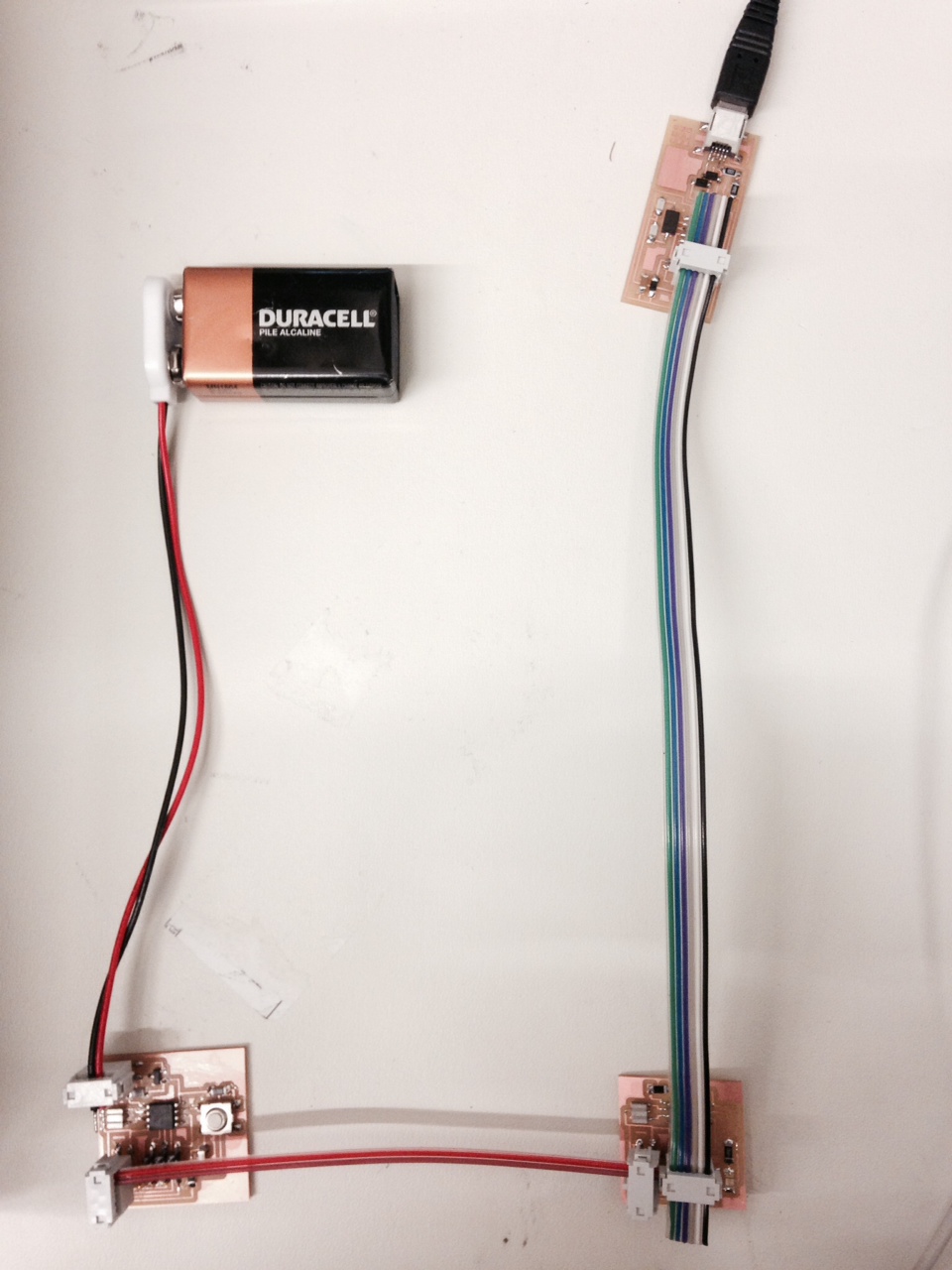
In the end, I was able to get both boards working and communicating with each other. Pushing the button on the master causes the LED on the slave to turn on
