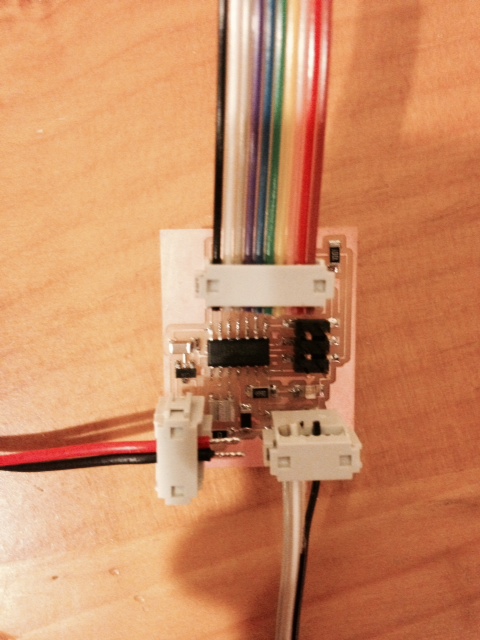
This week's assignment was to create and program a new board with an output device. I improved my board from last week (a board that includes a Hall Effect sensor and an LED) and added an LCD. Again, this is a step towards completing my final project which is a speedometer for my longboard. The completed board is able to count the number of times the magnet passes by the sensor within a specified time interval and then output that number to the LCD screen.
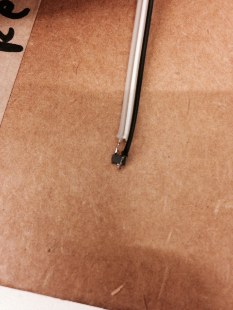
Again, I used Eagle to design the board (see previous weeks' examples). It is exactly the same as last week's board except that I added some contacts for the sensor so that it isn't soldered directly to the pins of the MC. This makes it cleaner and also more durable (over the past week, I have had issues with my previous board -- traces being ripped off because of external components being connected in awkward ways). I also made the battery and sensor connect with the removable connectors (like I should have done last week but I forgot).
For the LCD, I have 2 pins connected to ground (Vss and R/W), 1 pin connected to 5V (Vdd), 1 pin connected through a voltage divider (100k Ohm resistor and 1k Ohm resistor) to approx 0.4V (Vo), and 6 pins connected to digital outputs of the MC (corresponding to D4-D7, E, and RS on the LCD). This is according to the LCD's datasheet which can be found here and is set up exactly like Neil's LCD example here.
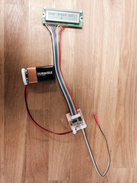
I used the Arduino IDE to program the board. Arduino has a library for communicating with LCDs so I just had to #include [opencarrot]LiquidCrystal.h> and the rest was very straightforward.Basically I just used last week's code and added a few lines to include communication to the LCD. Now instead of the LED blinking a certain number to times indicate how many events it recorded, it simply prints the number to the LCD at the end of the sample interval. The complete code can be found here. The most difficult part was figuring out which pins on the MC went with which pins on the LCD and how that would be interpreted through Arduino. I knew, for example, that pin PA5 of the MC was physically connected to RS on the LCD, but I had to refer to an Arduino specific Attiny44A pinout diagram to know how to call this pin in Arduino IDE (turns out it's Pin "5") and how to initialize it as the Reset pin through the LiquidCrystal library. Just google "Arduino LiquidCrystal" for an explanation of all the syntax you need to know and see how I used it in my code on the line where I initialize the lcd pins.
Another change from last week is I changed the variable type of anything that uses the clock (i.e. anything that calls millis()) from int to unsigned long. I was noticing a glitch after the program looped several times and I think it had to do with the variable overflowing. I got this hint from the Arduino website. Now it works exactly like I want it to.
I'm still going to iterate on this one more time for the final project. I want to get a bigger display. Hopefully I can find something that just outputs 2 or 3 characters on a single line. I also need to add in the math to convert count to mph (one line of code). Finally I need to add a button and a bunch of code that allows the user to input their wheel size to calibrate the speedometer. I already have a pretty good idea of how I will do this...I just need to figure out what kind of display I'm going to have for the final product so I know what kind of messages I can send out to the user.
Home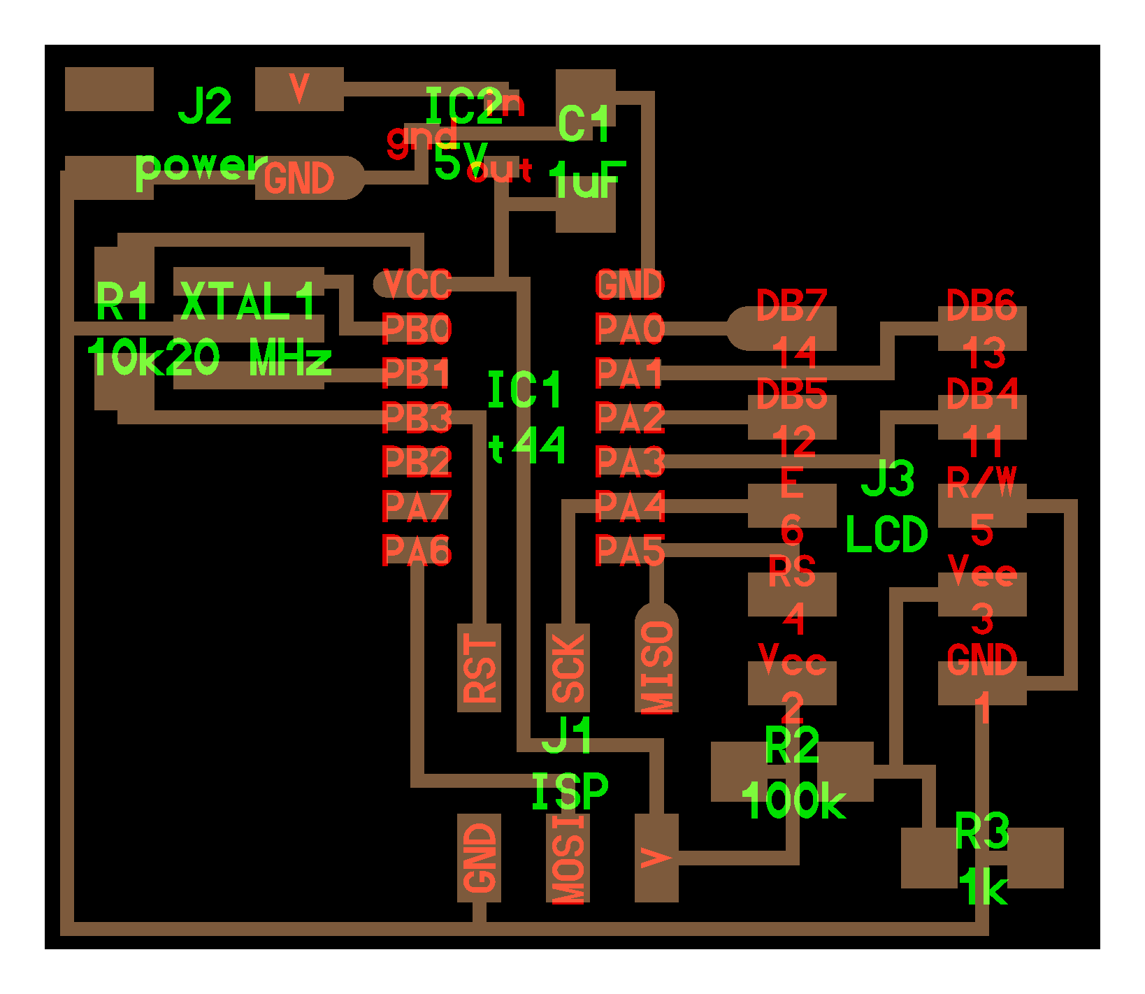