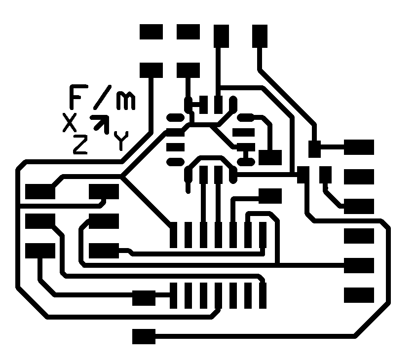
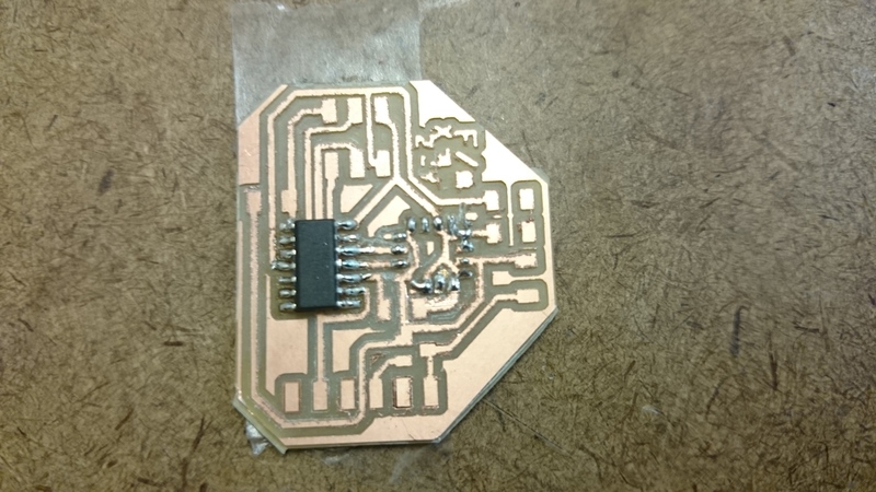
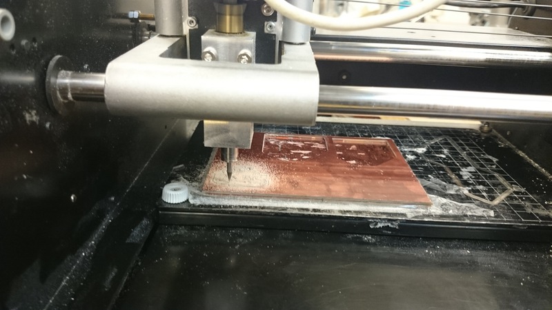
This week was remarkably frustrating. Initially, I decided to try to solder the 3D accelerometer -- not the tiny package one, but the one with the LCC-16 package. I didn't use the 2D accelerometer because it wasn't available in the Architecture section. Here is the board I designed and milled:
I used this tutorial to make add the accelerometer part to my eagle library, and I stole the LCC-16 package from the memsis library in the standard eagle library set.
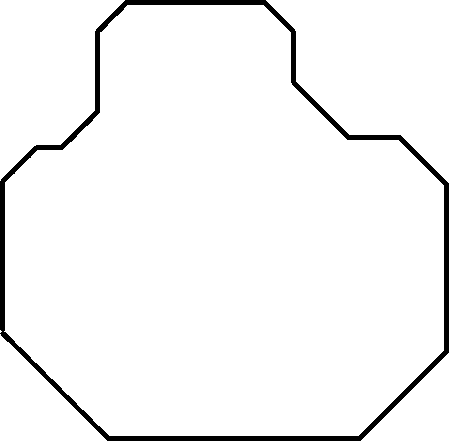
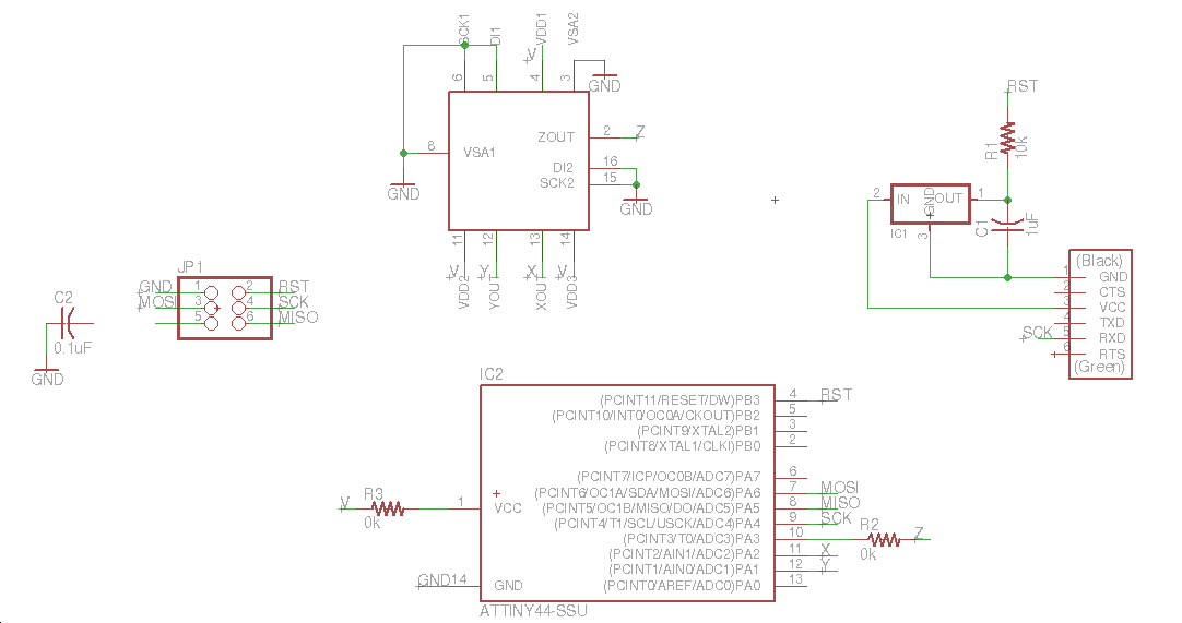
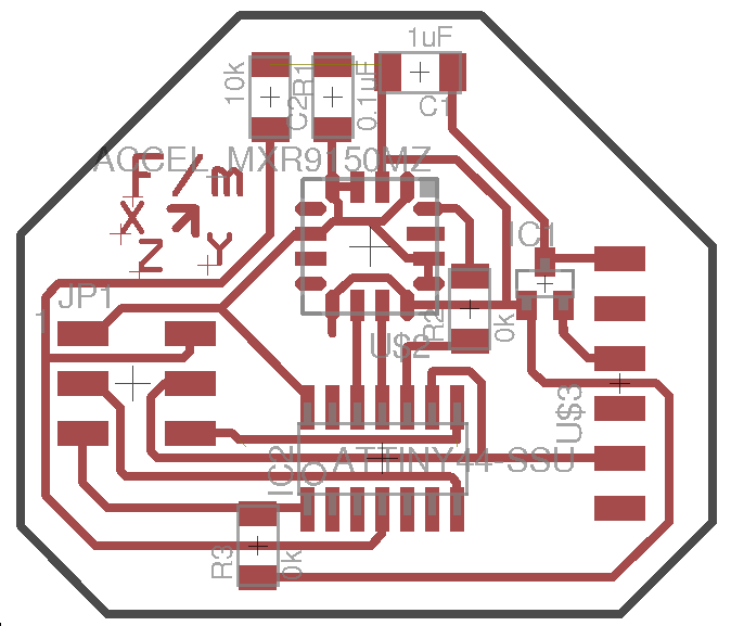
Schematic Board Traces Outline
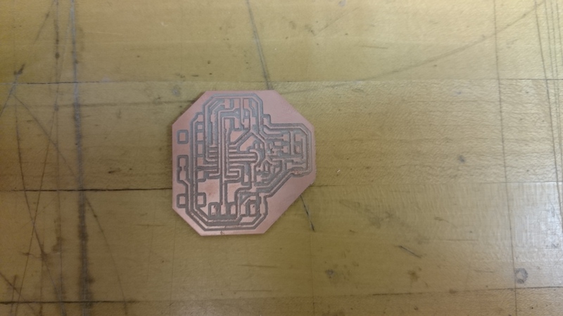
On the first try, I didn't notice that I hadn't quite designed my board to be whithin tolerances for the 1/16" endmill. You can see in the below screenshot the that, for instance, the traces under the attiny are not properly separated from the traces for the leads:
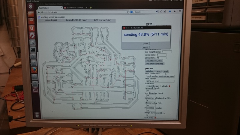
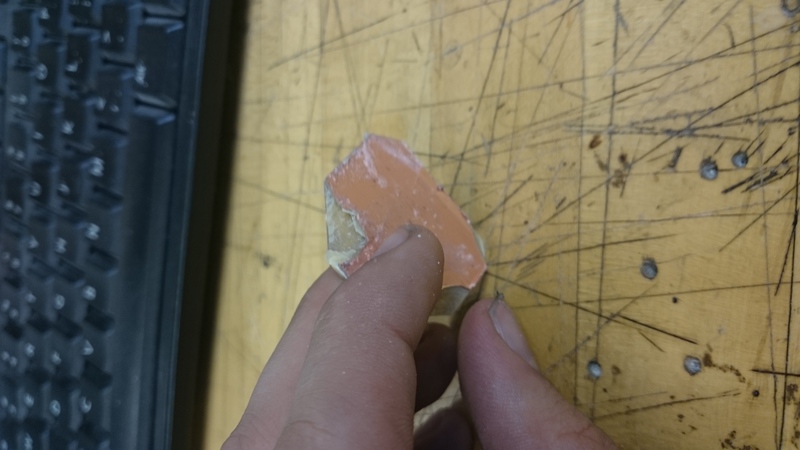
In addition, I had some more trouble with the outline cutting; namely it refused to cut the diagonal pieces all the way through, and left a bit of FR4 on the bottom of the cuts.. When I made the first board I was in a bit of a rush, so I just used the tool that is normally used for peeling boards off to break the remaining slots from the board. This is what broken off FR4 looks like.
I found that soldering the accelerometer was difficult. As Neil suggested, I tinned the traces and held the accelerometer in stream of a heat gun as a brought it down.
I was not able to program the above board when it was stuffed, probably because I went a little overboard with the heat gun and may have melted some of the components.
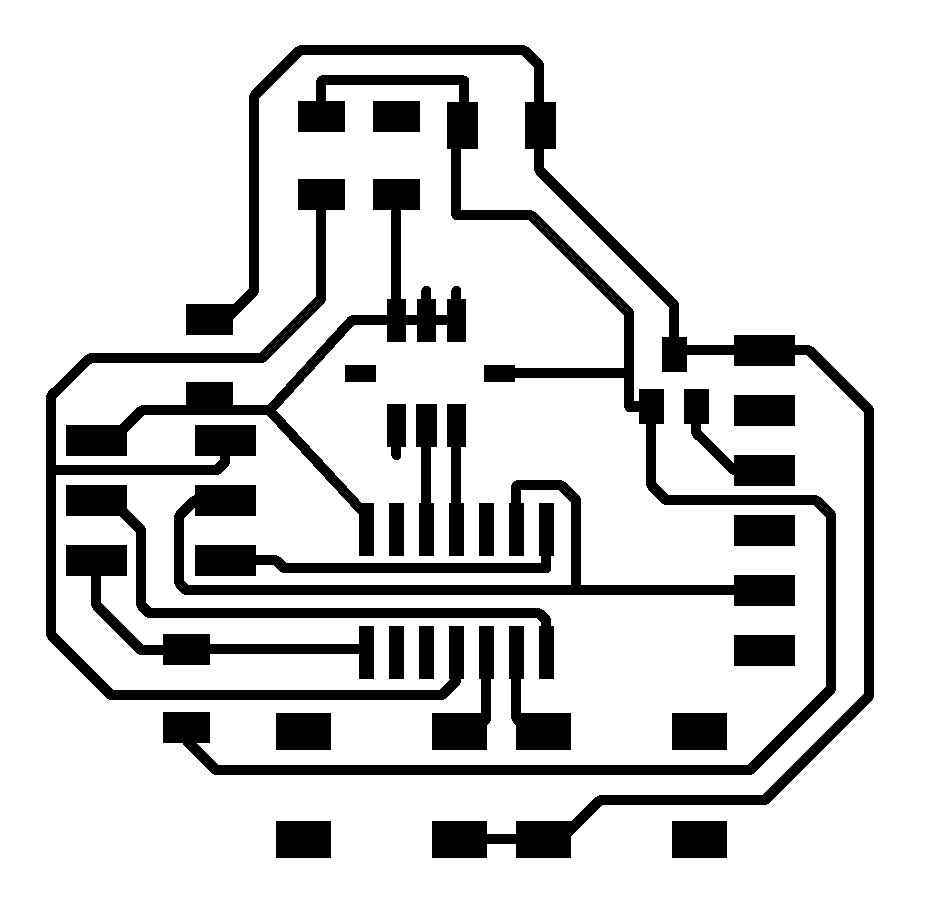
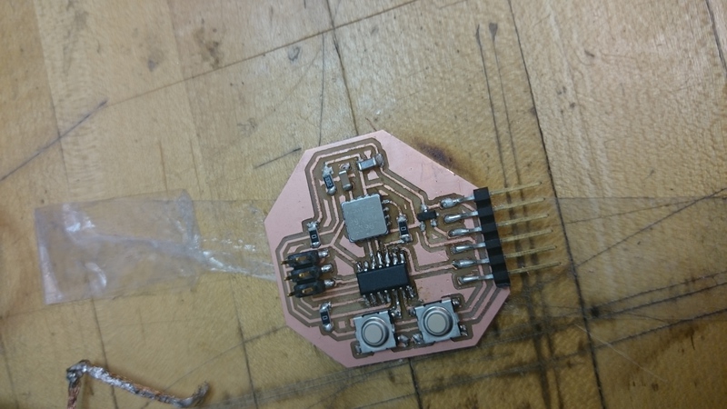
For my next attempt, I redesigned the board to make some of the spacing between traces better, and added two buttons because I thought it would be fun to make a mouse out of this chip during application programming week.
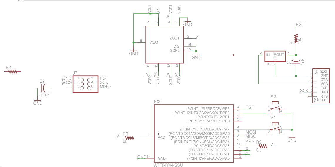
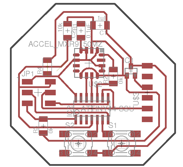
Schematic Board Traces Outline
I milled with the 10 mil endmill to make sure all the traces were right. Milling was straightforward.
Stuffing was again difficult. This time I tinned both the accelerometer and the board, and only tinned the pads that should make connection. I was also much more gentle with the heat gun.
This time, the board talked to me! Microcontrollers are like long lost loved ones; it's wonderful when you finally hear from them.
Sadly, it appeared that the accelerometer was not working. The X pin was always high while the other two pins were always low, and this did not change depending on orientation. I was not able to debug this issue. Instead, I got some 2-axis accelerometers from the CBA shop and used them in my design instead.
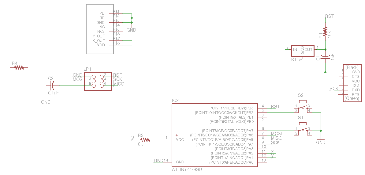
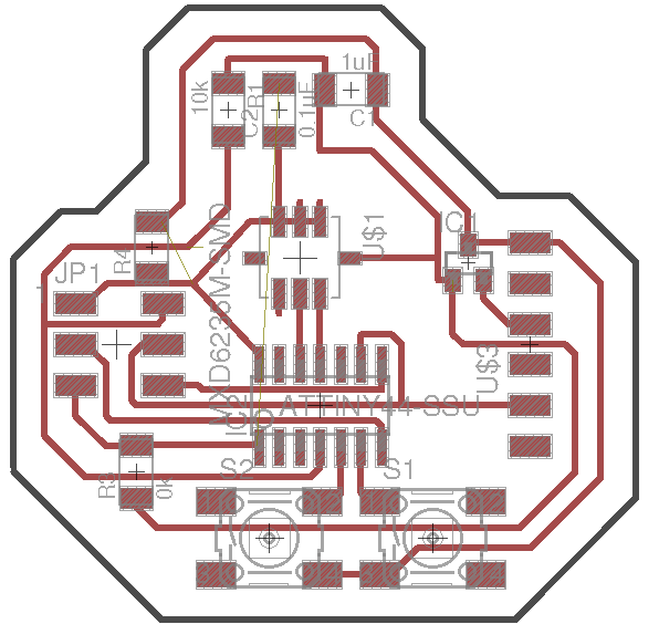
Schematic Board Traces Outline
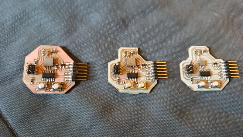
Here is the new design milled and stuffed, to the very right
of two other boards (the other boards is are of the
second design; the first didn't talk to me while the second did).
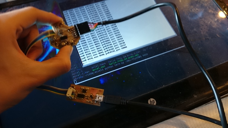
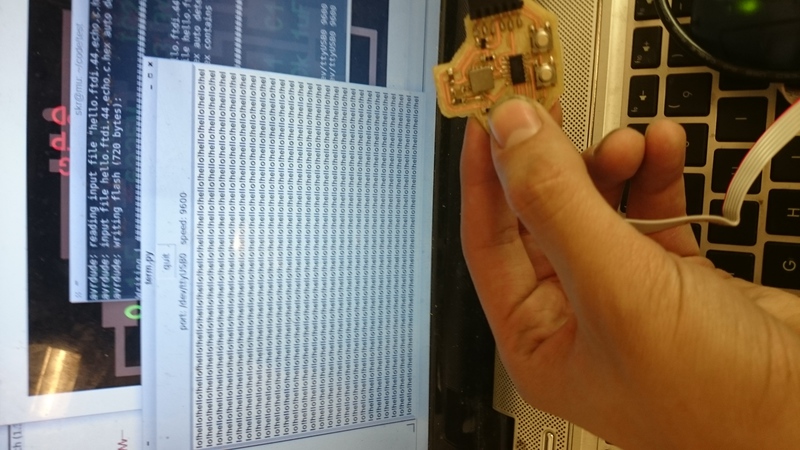
This one talked to me and worked flawlessly. I modified neil's accelerometer code to output text:
Here we are, reading a sensor!