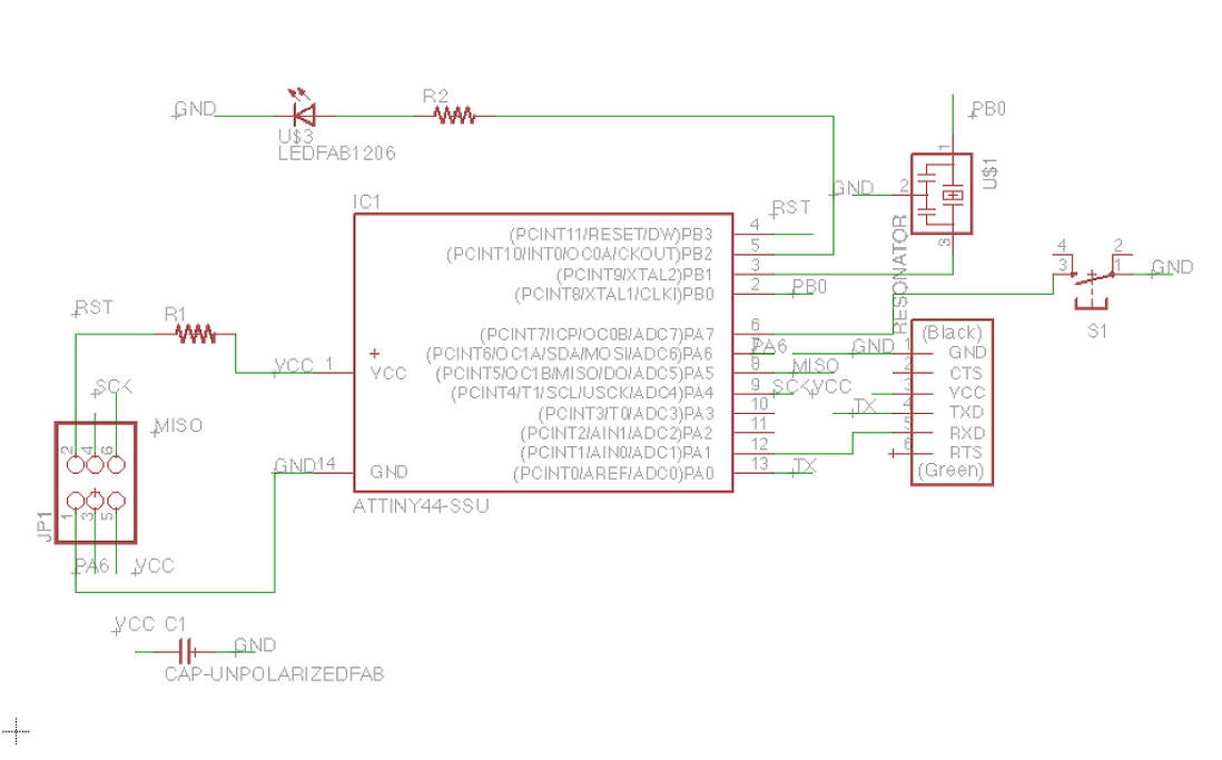
I started with designing the borad in Eagle. It took a great deal of time to get used to the software. After loading the fab and the fab_copy libraries into the software, I put in all the parts that were needed and made all the connections. Net and wire are the two commands to use while making the traces. It is better to label all the connectons right at the beginning. This helps in avoiding a lot of confusions later. Once all the connections are made, its a good option to check by using show 'component name' command. This highlights all the similarly named components and connections. Its time to sort out the mess in on the board.
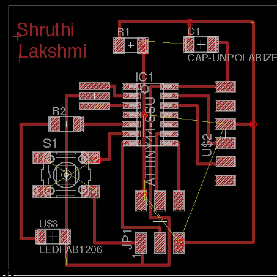
It was a quite a mess when I switched from the schematic to the board view. It took a while to clear it out. Rats is a pretty useful command to know while trying to make the traces look cleaner. It removes all unnecessary connections.Sometimes, you can ignore the yellow lines(these are the traces that re not routed yet) if you are sure that you are making the right connections. Once you are in the board view, its all about playing around.
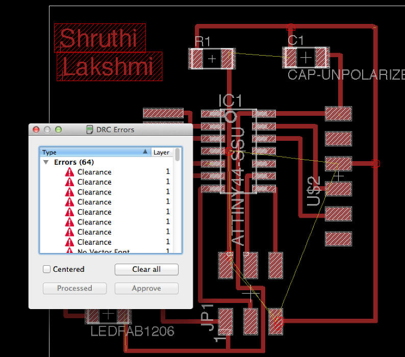
I kept checking for the clearance every now and then. There were two traces that were too close to each other. While moving these traces around to a better position, one good option is to reduce the grid to 0.01 from 0.05. This helps in moving the traces to minute distances.
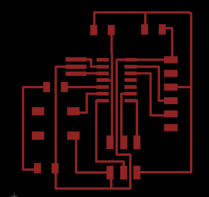
Final trace. Initially I had directly imporated the same image without saving it in monochromatic format. The fab modules will not be able to calculate the path if its in colour. So I had to resave it in black-and-white and calculate the path.
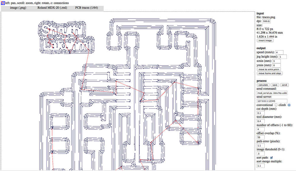
Trace settings. I had to reduce the tool diameter from 0.4 to 0.3 as there were a few connections that were not complete. Though this posed a problem of the traces becoming too thin, Rob and I decided to go ahead with it to see if it works out fine. Everytime, a printing job gets done, its a good idea to reload settings in mod.cba.mit.edu. Though this not an entirly necesssary step, I found it to be quite useful.
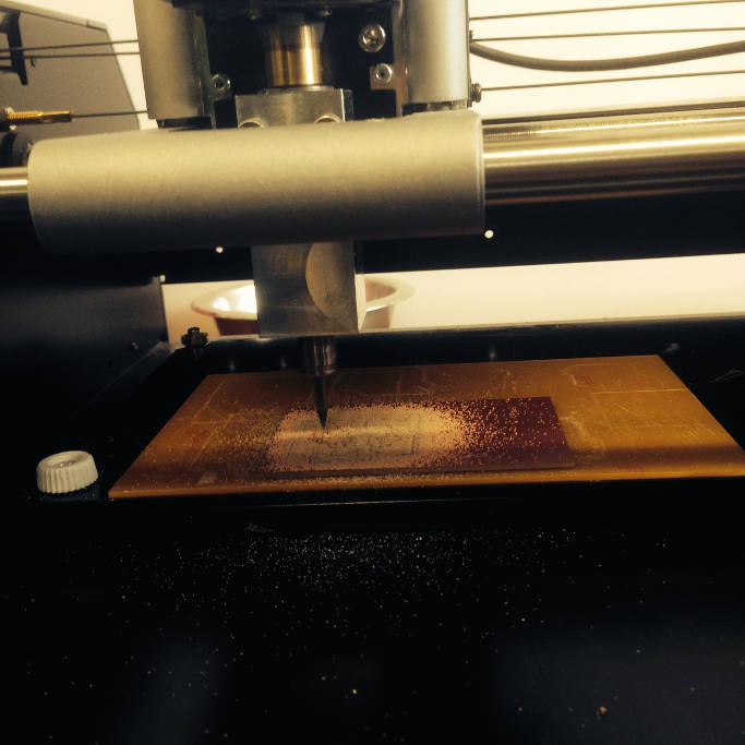
Printing in progress.
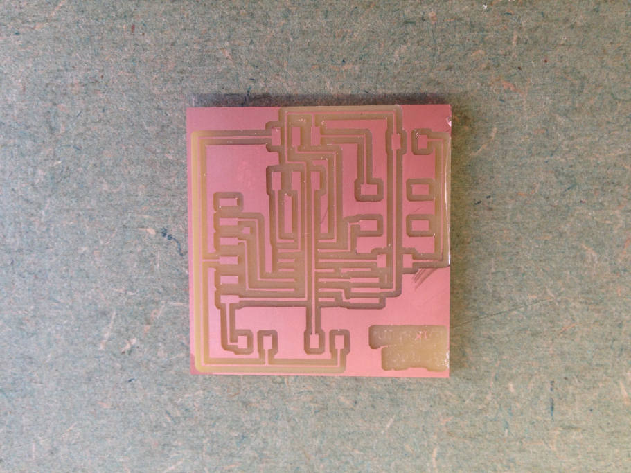
Printed board. As you can see, since I reduced the tool diamter, my name dint get printed out and you can a void right there at the top left corner. I was thinking about printing out another borad but decided against it.
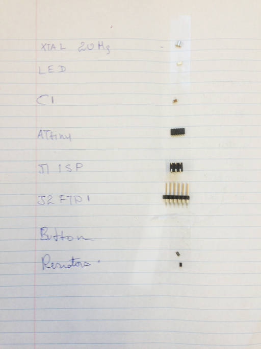
It was time to go scrounging for parts.
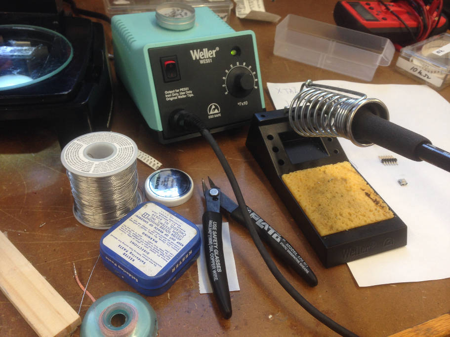
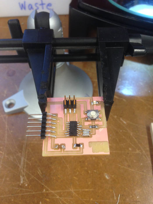
Tools set.
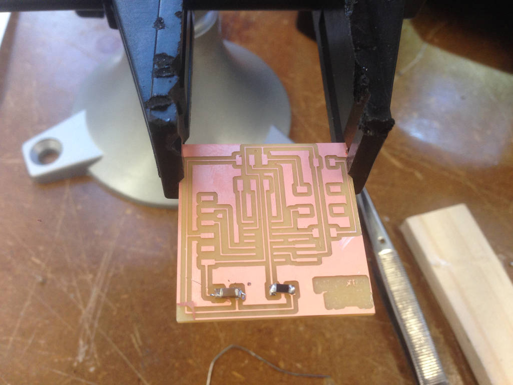
Soldering time! this time it was much easire and faster. I was able to finish soldering in approximately 30 minutes.