How to make (almost) anything

by Thrasyvoulos Karydis

Computer Controlled Machining

Intro: OSB Legos

My initial idea for this week was to create an ensemble of different OSB lego pieces. It didn't require an elaborate design, but I was sure I would have to experiment with different depths and sizes to get a nice result. I was worried that the 
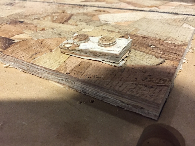
OSB would be too thin for nice structural properties (spoiler: it was!) but I decided to give it a shot. To design the 
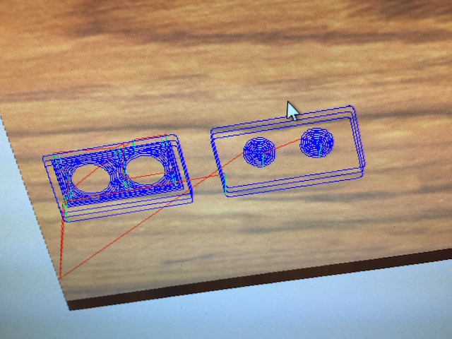
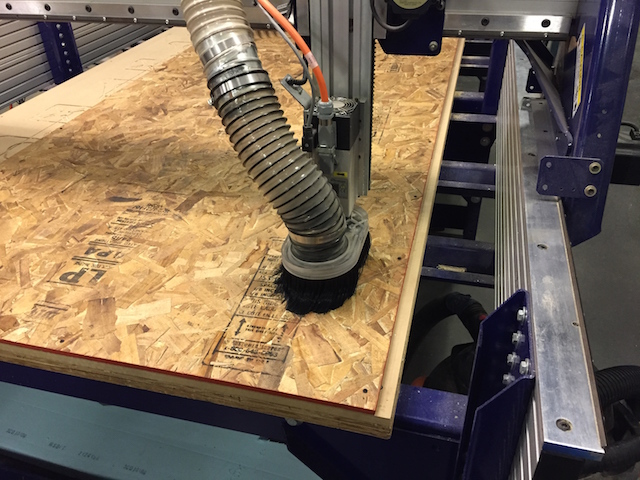
legos, I went straight to pc interfaced with the Shopbot machine and used Partworks3D. In such a way, I could have immediate feedback for the size of the lego and the protruding parts, in reference with my tool diameter.

After a lot of trial and error between tool diameters and pocket sizes ("how to" on Step 3), I ended up having a design where my tool - 0.125 endmill - could create the desired lego shape.

Now the tricky part: aligning the "female" holes in the bottom side of the lego brick, with the corresponding "males" on the top side. In order to do that, I marked with a marker the outline of the OSB piece I worked with, so that I can flip it over and place it in the exact same position ( click to see images on the right). After everything was in place, I created the three toolpaths -one for the top side, one for the bottom side, and one for the final cut- by changing what area would be pocketed.

UPDATE: Change of plans

As you can see from the previous image, OSB is too thin for a proper lego brick. That's why I proceeded with making two different partse one "male" and one "female" and stick them together, instead of a single double sided one. Yet, I realized that with this process I would need ages to reach the "make something big" objective. I tried to order a thicker plywood, but I didn't have enough time for it to arrive at the lab, thus I decided to do another project for this week. Since the Shopbot training, I wanted to create text engravements on OSB and experiment with different depths and endmills for detail. I seized this opportunity to create something nice and funny for my brother.

Step 1: Creating the drawing

My brother likes a lot chemistry, so I decided to create a big engraved chemical element with his name. The first step was to generate the image/text I wanted to engrave. I found a cool website called MyFunStudio.com which had exactly what I was looking for: a periodic table writer! Using this interface,you can write arbitrary words and have them spelled using chemical elements.

You can see the generated output on the right, with my brother's name spelled. Unfortunately, the created image was not vectorial, so it was uncomfortable to use with CAD software (resize,etc.). Yet, I found another awesome website, Vectormagic.com which takes as an input an arbitrary image (.jpg,.png,...) and traces the edges using an edge detection algorithm in order to transform the image to a vectorial 2D mesh. As my image was just black and white, it was very easy to be traced and the result was a fine, scalable PNG image.

Step 2: Generating the toopath

To create this week's project, we will be using the Shopbot, i.e. a large format machine that is controlled though a computer interface. Computer controlled machines typically have a set of actuators to provide degrees of freedom in motion, and can receive a toolpath, i.e. a set of coordinates to move the head (spindle). For the Shopbot, the toolpath files have the .sbp extension and if you open them with a text editor, they look like the image on the right. In the begging there is information about the dimensions of the material you will be cutting, the endmill being used, as well as the cutting depths. The rest of the file has commands to the spindle head, which consist of the type of the command and the coordinates of where it should be executed.

To generate the toolpath from the PNG image, I used Partworks3D, a software which comes along with the Shopbot. The interface was staightforward, but I would recommend going through one of the tutorials here first to grasp the basic ideas behind the toolpaths for Shopbot. I made sure that the image vectors were connected where they should be, and moved on to generate the toolpaths. I created a pocket toolpath for each letter I wanted to engrave, and a profile toolpath with tabs to cut the piece out of the OSB. After getting feedback from the 3D preview, I decided to use a .25 inch endmill in order to fit around the tight pockets of the numbers in the image.

Step 3: The shopbot

After exporting the .sbp files (toolpaths), it was time for action. I loaded the OSB board on the Shopbot, and mounted the 0.25 inches endmill in the collet. I set the spindle speed to 10.000 rpm which judging from previous years should be enough to cut smoothly through OSB.
The pocket process lasted around 20 minutes, but the result was nice. There were a few places where the 0.25 inch endmill could not fit, but I decided to proceed. For the profiling (cutting out the engravement) 2 passes were needed as the depth of the OSB was close to 2 diameters of the endmill.

Result: Cool Gift for Bro!

The resulting quality was higher than my expectations. The OSB was cut cleanly, without spikes or detached pieces of wood. I think that a varnish coating will be a nice finishing touch for my creation. Unfortunately I could not get a varnish paint until the next class but I will update the page as soon as the paint-job is finished!

** Click the image for more images of the OSB engravement. **