How to make (almost) anything

by Thrasyvoulos Karydis

Intro: Charlieplexing

This week we had to play with output devices. I knew what I wanted to do right from the first day: Charlieplex an 8x8 RGB LED matrix! If you actually make the calculations the resulting number of LED's needed to be addressed are: 192!! Thankfully, due to a guy named Charlie Allen there is a technique to address those LED's using only 19 pins! This technique The method uses the tri-state logic capabilities of microcontrollers in order to gain efficiency over traditional multiplexing.

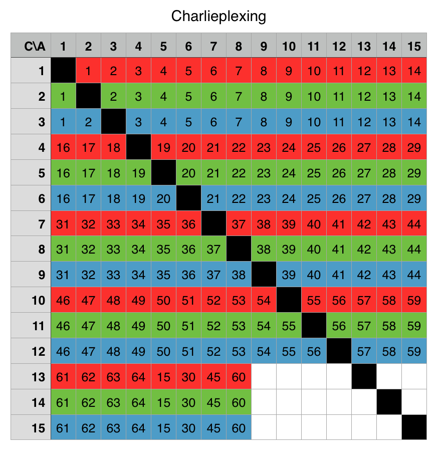
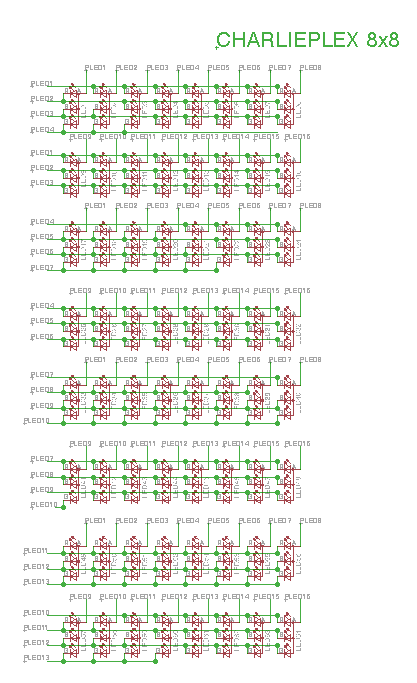
The trick is that if you change the directionality of a single pin, it can act both as an anode and a cathode for an LED. Moreover, the tri-state has a very high impedence so the pin is like being totally disconnected. To simplify the design of the charlieplexed pins, I made the matrix you can see on the right. Each column and row number represents a pin. Each pin is written two times because it can act both as an anode (columns) and a cathode (rows). In the produced array, I can place each LED either horizontally or vertically, depending on whether the LED's I use are common anode or common cathode. The diagonal of the matrix is black because I cannot connect both the anode and cathode of an LED to the same pin as it will short-circuit.

The schematic!

After creating the array , I had to transfer it to the schematic in Eagle, a thing which proved to be really really really time-consuming, even if it was kind-of straight forward. The end result though seems quite intriguing. Yet, eventually, after trying to route the board I realized that this schematic was not helping at all, as the LED's where not in an 8x8 array, which would be the final topology. Thus, I rearranged the LED's into the appropriate topology (click on the image to see) naming the wires and using labels to guide me. The final architecture seemed quite intuitive but I don't think that it is possible to wire such a board using only one layer.

The board!

Firstly, I want to be clear: I strongly do not recommend to anyone trying to route 192 LED's Charlieplexed board using only one layer of wires. I initially considered it as a challenge, but after >5 hours in front of the screen scrathing my head and moving wires here and there, I realized it was too much of a hurdle. Thus, I ended up routing half the board and doing a supervised auto-routing to the LED array in two layers. I increased a bit the size of the holes so that I can mill them with the 1/32 inch endmill, but i couldn't manage to separate all the wires more than 10mils, so I will have to use the 10mil endmill for some clearances.

Milling a two sided board

I started the milling process using a 1/64 inch endmill to clear most of the top layer's wires and pads. After the job finished, the board was 90% cleared but it had some places where the endmill couldn't fit so I ran another job using the 10 mil endmill. Unfortunately I send the toolpath for the whole board again, and I could not cancel it through the compiled fab modules so I waited another 30 minutes for the new job to finish.

Before swithing to the second layer, I ran the job to drill the holes using the 1/32 inch endmill. To my frustration the holes were not drilled all the way, which I thing was due to the sacrificial layer being a bit tilted in the middle. Luckily, after running the job again the endmill went all the way through without losing the alignment.

Having the first side ready to go, I flipped the board and aligned it to the edges of the sacrificial layer, hoping that the bottom layer will be alighed with the top. I also flipped the bottom layer PNG file in Gimp, so that it can match the flipped board. Unfortunately though I made a foolish mistake: I left the Xmin and Ymin positions the same! As a result, the whole bottom layer was 1 cm to the right of it's correct position. Nonetheless, I planned to cut the board and wire the bottom layer using a set of external wires to connect each hole with each other. Yet, I guess it was not my lucky day, as the alignement proved to be a bit off and the through-cut cut around 5 mils of the bottom of my board, destroying completely some connections and pads. It was a bad day :(

Life Lesson: An LCD equals many LED's

As I had no more time left for this week's presentation day, I decided to postpone my output project and mix it with networking. The resulting work would be the "output module" that I will use in my final project. After spending so many hours with the LED's I decided to switch to an 16x2 character LCD module, which would make things a lot simpler. I might return to Charlieplexing later but it is acually better for me to use an LCD display now as I mainly want to have text as output. You can see the LCD module on the image here, and you can find information about creating, milling and stuffing the board in the next week's page. In the rest of the page here I will focus on programming of the LCD module.

UPDATE: Programming the LCD screen

Programming the LCD screen was easier than I would ever expect. I found a library for lcd screens interfacing from 8051projects.net, which had all the typical functions already there. I just had to tweak the ports and control bits (Enable, Register select) to correspond to my microcontroller (ATMEGA32A). I will write/quote here a short overview about talking with the LCD module to be consistent, but the tutorial on the link above is exceptionally good.

It comprises of two registers: the instruction register and the data register. Before starting the internal operation of the LCD, control information is temporarily stored into these registers to allow interfacing with various MCUs, which operate at different speeds, or various peripheral control devices. The internal operation of the LCD is determined by signals sent from the MCU. These signals, which include register selection signal (RS), read/write signal (R/W), and the data bus (DB0 to DB7), make up the LCD instructions. These instructions regard mainly the position of the cursor on the screen and shift/clear commads. In every output iteration you first set the cursor where you want, and then fill in the data register with what you want to be displayed. Oh, and don't forget Lcd_write()! (On the image in the right the 8 after Lcd, means it talks to an 8bit processor).