This week we learned about PCB fabrication. The goal was to make the FabISP AVR programmer, in order to be able later on to program our next boards.
The PCB was created by milling and not etching a copper on a board. This is a much more straightforward procedure for small volume applications (i.e. prototyping) as it does not involve chemicals and masking.
Step 2: The board!
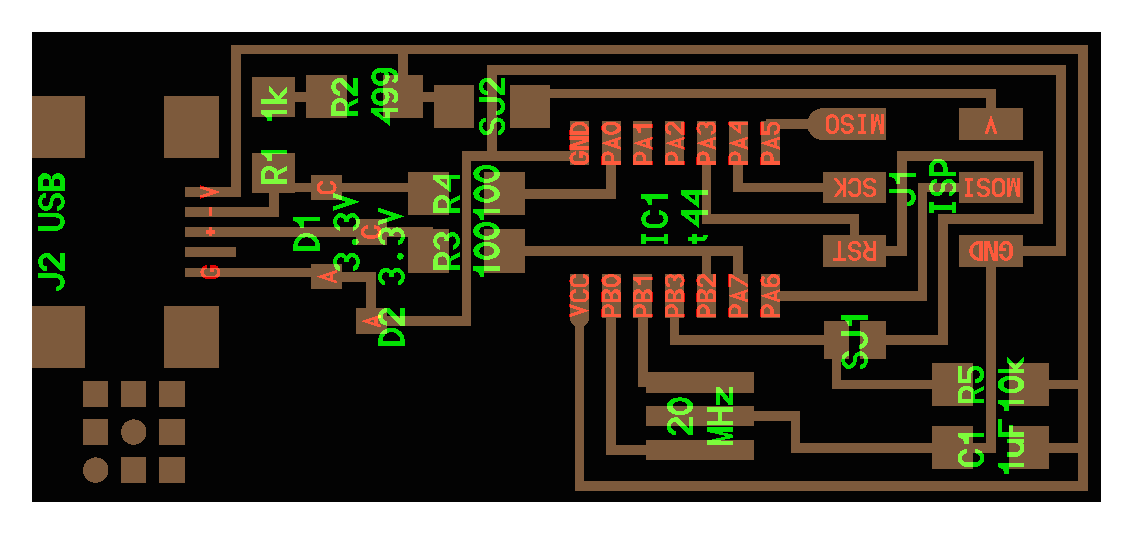
I chose to create the circuit with the 20MHz resonator. Here you can see the circuit diagram, and the milling outlines.
The circuit is comprised of the ATtiny44 microcontroller, a mini USB port, a 6-pin jumper and a 20MHz resonator, along with other passive and active components for current/voltage protection.
Click the image to view more images of the circuit board.
Step 3: Milling the board
First try
To mill the circuit board, I used the Modela milling machine.
First, I put double sided tape on the back of the board making sure that the board was taped down properly on the sacrificial layer, i.e. a bigger board mounted to the base of the Modela so that we don't damage it when cutting the board.
After setting the (x,y) to (0,0) using the compiled Fab Modules, I zeroed the height of the end mill - z axis - so that the tip would touch the board surface.
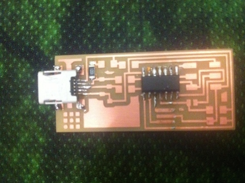
There are two kinds of end mills that we use for making the board. The first one (1/64") to "mill traces" and the second end mill (1/32") for cutting the board. As you can see from the following image, my first attempt was not that successfull - the board did not cut properly (I used it for soldering training though!). I believe that the reason it didn't cut was that the sacrificial layer - a large board placed underneath the object being milled - had too many traces on it.
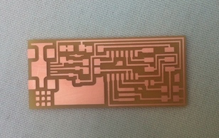
Second try
For my second trial, I used a new sacrificial board and the final board looked great!
Note that in the 1/64" milling I used -0.2 as the setting of z-axis (cutting depth). For the 1/32" milling I used the default fab module options.
Now that I have the milled board, it is time to stuff it! As you can see from the bad milled board image above, I trained a bit to remember how you solder and when I felt I can have good results (and my nose got used to the smell), I started soldering the parts.
Step 4: Soldering
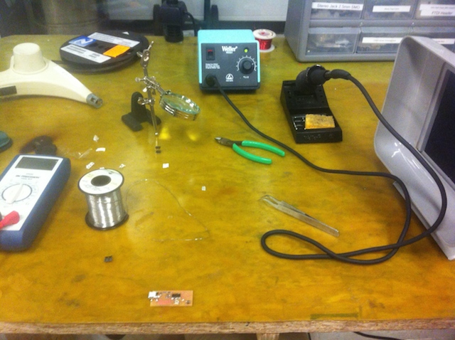
The setup
Prior to soldering the parts to my board, I had to prepare the desk for the soldering process.
Tools needed:
- soldering iron
- fan for exhaust fumes
- lead solder
- tweezers
- multimeter
I decided to use solder with lead for this project, as it's much easier to handle than the lead-free one. My solgering iron was heated up to 720 degrees.
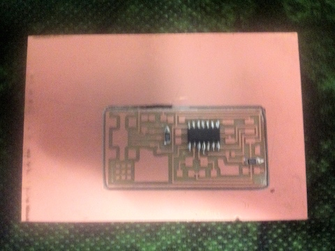
First parts on place!
First, I soldered the larger parts, i.e. the mini usb port and the Attiny44 microcontroller. After a bit of practice it turned out to be really easy to solder multi-pin components. Yet I still have to master the drag-soldering technique (see video here).
Thinking a posteriori, I should have soldered the smaller parts first, as the bigger ones blocked my access to the former.
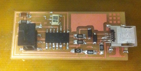
Voila!
After a an hour of lead fumes inhalation and frustration, the final result looks promising and ready to be programmed! I used the multi-meter in the continuity mode to check for shorts, and everything "sounded" nominal.
Step 5: Programming!
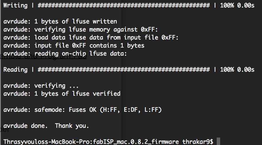
To program the.. programmer, I used the AVRISP programer from ATMEL (see image) and followed the very well documented istructions in this page.
I didn't run into any problems, although my programmer is not recognized from my Macbook. Yet, it works with avrdude to program other boards.
After I programmed the FABISP, I desoldered the 0 Ohm resister and the solder blob to free the RESET pin.
