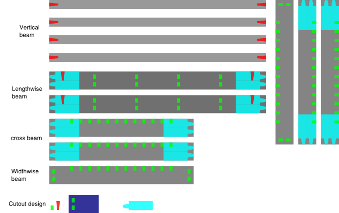
Inkscape model of pressfit box design
I started out designing this week by sketching up some ideas in OneNote. Unfortunately OneNote likes to divide things into pages when you try to export (it is a note taking program after all), so I wasn't able to get a good single image of my sketching. Here is my Inkscape model instead. In short, I expanded a bit upon my week 1 idea to try and make a specialized moss growing structure. Moss is an interesting and somewhat understudied model organism. I'm interested in studying the metabolites of moss, but this requires a *lot* of biomass. Right now, you can grow moss at a smallish scale on petri dishes, where it will go through its entire lifecycle (leafy structure etc.), or in largescale liquid culture, where it remains as disorganized cells. However, the disorganized cells from liquid culture isn't too appealing if you want to study natural metabolites, as these might only be present in certain tissues etc. The idea for the design was: if you could grow a lot moss on large vertical surfaces, and it would pass through all the life stages, maybe you could collect enough moss for detailed study of its metabolites throughout the lifecycle. Okay, thats my somewhat justification for this design, but in actuality it was more just practice making something big. I decided to go with pressfit as I think that is actually a pretty elegant solution. Yet again I used Inkscape for my modeling tool, as at this point I know all its tricks and nothing necessarily called for 3D design. I put the cloning trick Neil demonstrated for the laser cut pressfit assignment to good use again, this allowed me to easily propgate changes to the pressfit across the design. A short description of the design: It is a box, the top or bottom face is defined by 2x "lengthwise beams", 2x "widthwise beams", 4x intersecting "cross beams", which pressfit together. The vertical structure comes expectedly from the "vertical beams" which pressfit into the lengthwise beams, thereby connecting two faces to make a box.
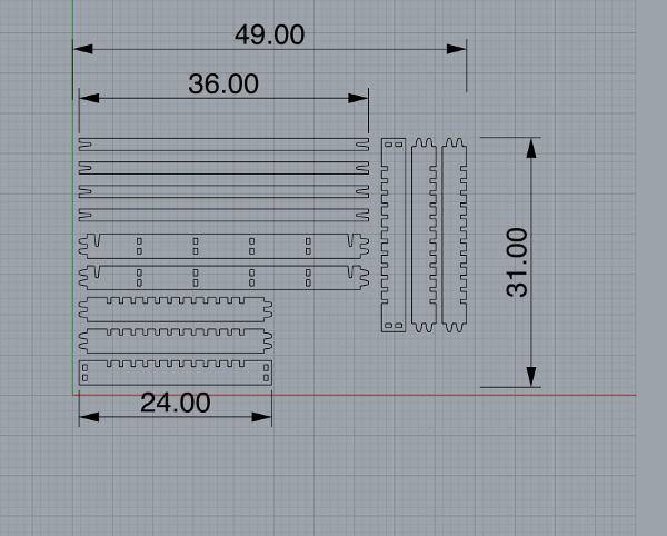
The model in Rhino
I then moved my model from Inkscape into Rhino by exporting as a .dxf file. This was due to the fact that MasterCam (The toolpath producing program for the Onsrud), could read the .3dm Rhino files. A point when moving between programs: make sure to keep track of units! In my case, I worked in Inkscape in inches, exported in inches, and worked in Rhino in inches, and that worked out fine. As much as I prefer metric, all the machinery thinks in inches so it was easier to keep track of. I used the CurveBoolean tool (Curve->Curve Edit Tools->Curve Boolean) in Rhino to properly change the overlapping shapes from Inkscape into actual polylines of my geometry.
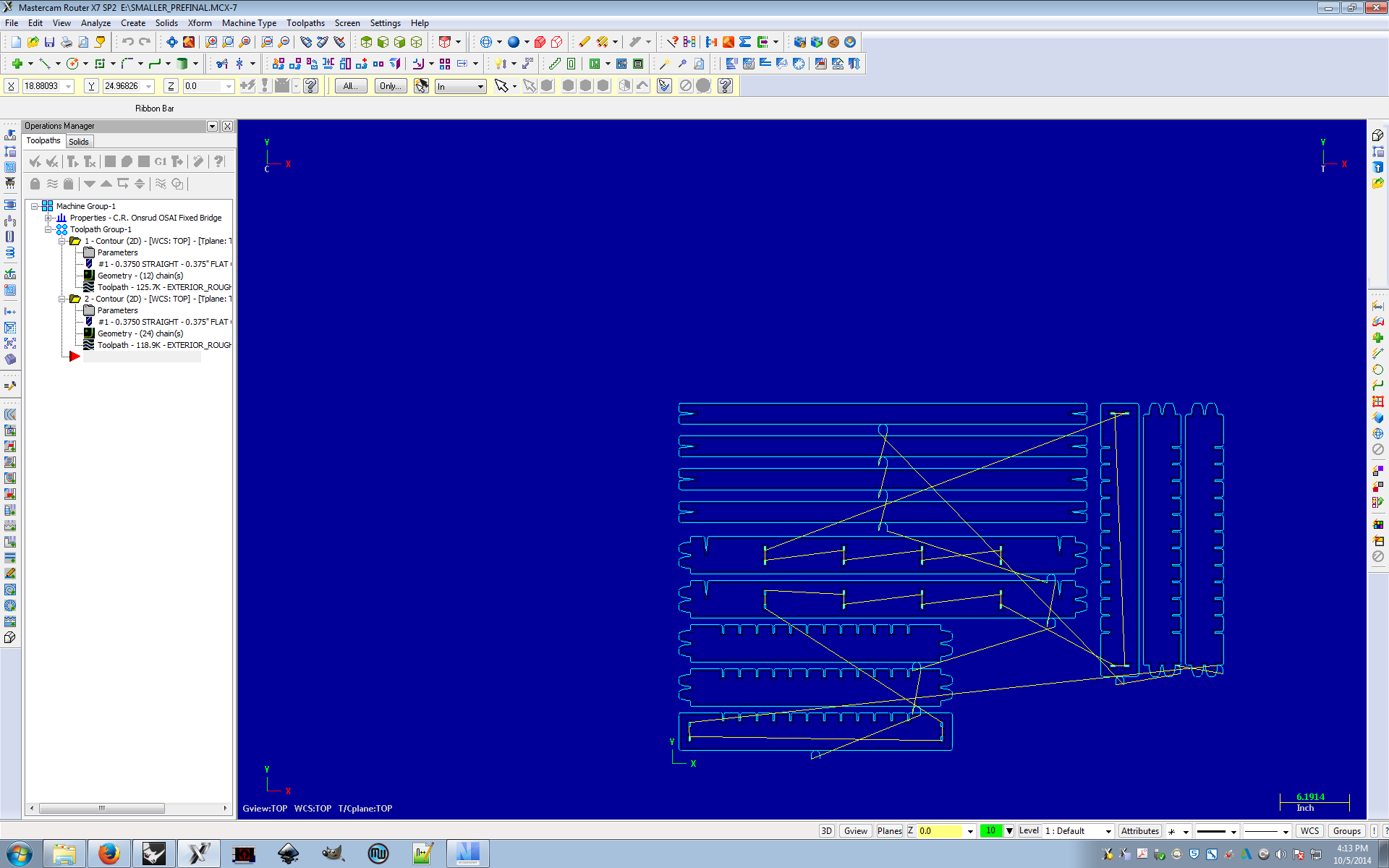
Making the toolpath in MasterCam
I then transfered my model from Rhino to MasterCam. This was really where the majority of my time on the project this week was spent. MasterCam is a very powerful, and incredibly obtuse piece of software. The image above shows my attempt first attempt at designing a MasterCam toolpath. I made two rough cut toolpaths, one for the exterior of the geometry, and one for the internal cutouts. They both used tool #1 (0.375" compression tool). Had I actually used this toolpath, it would have been pretty crappy results likely, as the lack of a finishing pass means the corners and insets would have likely not the shapes I wanted. But before running this toolpath, I ran into some issues. Firstly, I hadn't yet figured out how to properly specify the height of the stock. This led to the software thinking the stock started a Z 0.0, and from the simulation I could see the toolpath dragging the tool everywhere makes cuts where it shouldn't. The other issue, the lead ins/outs (The curved sections where the tool goes up and down), were cutting into different parts of the model. Unable to figure these issues out, I called it a day.
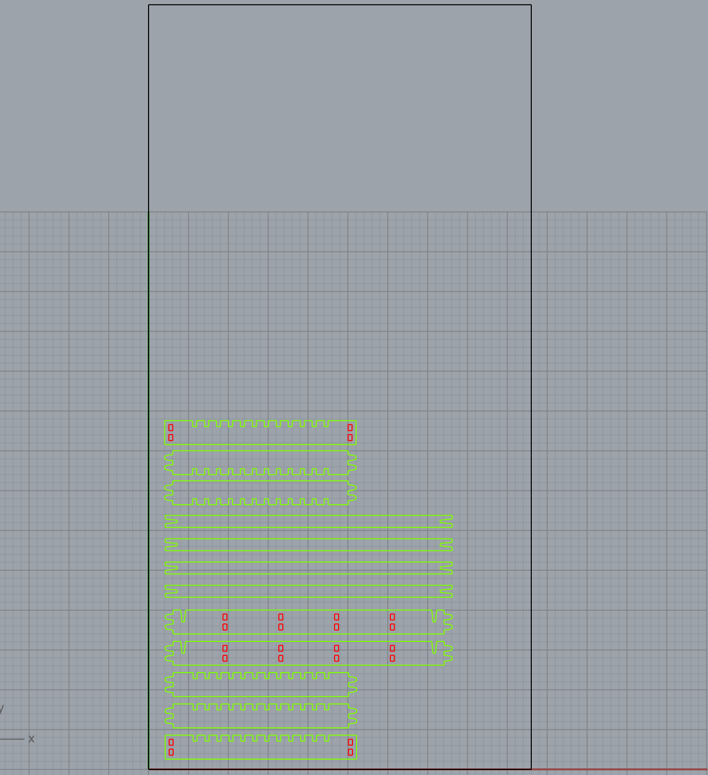
A revised model in Rhino
The next day, Architecture RPL guru David Costanza was able to give me a few pointers on the correct way to go about using Rhino and MasterCam. Firstly, he setup my Rhino model so it had a bounding geometry outlining the stock (OSB 4ft x 8ft, long axis of the machine vertical by convention), as well as put the interior geometry on a separate layer from the exterior geometry. This made downstream toolpath generation quite a bit easier. For MasterCam, the tricks were many. A particularly good one, if you're interested in changing the geometry of your design, without destroying the time put in to define the stock, tools, feed rate parameters etc, you can delete the existing geometry, use the File->Merge operation to import new geometry, then right click on the geometry part of the toolpath (if this doesn't make sense scroll up to the picture of MasterCam), and add the chains of your new geometry. The "window" selection on the chain adding dialog allows you to easily drag a box over the geometry you want to select. The key is the layer trick from Rhino. Layers in MasterCam are called levels. Down along the bottom "menubar" it says Level, clicking into that allows you to selectively hide/show levels. By only showing interior or exterior geometry, you can easily select the geometry you want for a particular toolpath type. This is important as MasterCam defines contour cuts as either "left" or "right". If that isn't set correctly, exterior cuts will actually cut into the interior etc. Ultimately, we setup 4 toolpaths, a rough cut with tool #1 for the exterior and interior, and a remachining cut with tool #2 for the exterior and interior. In particular, the remachining cut used the "remachining" countour type in parameters (with the tool diameter of #1 correctly defined). This meant that the router would only try and remachine the places where it thought tool #1 had missed. A neat trick for a highly efficient job. Ultimately everything was in order, and it was time to actually use the Onsrud. To export Gcode, you use the highly obtuse icon of "G1" seen in the icons above the toolpath stuff. Set the UAO table height=1 when exporting. Save the file with less that seven characters and the Onsrud can only handle so much. Then, put the .NC file on a USB stick and walk it over to the Onsrud.
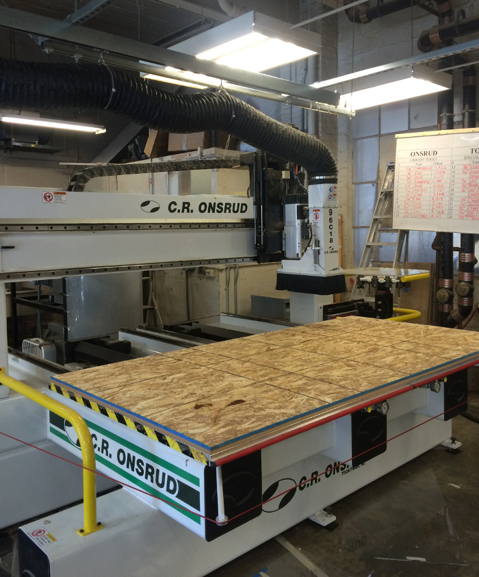
The Onsrud in all its glory. - Pre stock cutting
The Onsrud is an awesome big physical machine, which means it should be feared and respected. Chris Dewart, the manager for the Architecture wood shop did a great job helping me setup the router and run my job. What I can remember of the startup procedure: There is a spindle warmup procedure saved on the machine somewhere, this is run first. After this was done, the two vacuum pumps were turned on using the switches on the wall (right hand side). Next, the yellow buttons under the stock table should be pressed, which opens the table to the vacuum and pulls the stock down. You then move your .NC file from the USB drive to the "UPP" folder on the desktop of the machine console. Open the .NC file by clicking the button along the bottom right labeled "Part selection" or something (Apologies to anyone actually reading this to try and get insight, this was all very hands-on so I'm forced to write notes from memory). Verify your NC file by physically walking over to the tool heads in their holder, making sure they are the right tools, and that the UAO option in the Gcode file is set to 1. Next, if you so desire (I did) you can "air cut", but making changing the Z offset value to some positive number (couple inches), and hitting the green square "Go" button. After hitting go, the machine will go through some of the motions, only above the stock. The big square yellow button on the console is the reset button ending the run. If the aircut looks good, stop the run with the yellow button, set the Z offset back to zero, and hit green to cut for real. Your part should begin getting milled! Some other notes on the instrument: If you accidentally trip the red cable around the instrument (I did), the machine will go into Emergency Stop mode. You have to reset a physical switch where the red cable meets the machine, and hit the big green button on the console to get it back into normal mode.
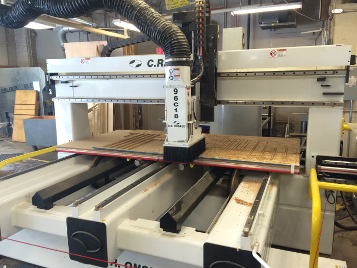
The Onsrud in action
A nice action shot of the Onsrud in action. Also some words on the material we used this week, known as oriented strand board or OSB. The words I would use: Splinters, cheap, and strongish. This is the type of wood you typically see boarding up abandoned industrial lots, but hey, its a cheap, actually somewhat strong material thats a great choice for learning on. In fact, the "finish" on the edges of my cuts, a notoriously tricky aspect of machining, was actually quite good. I didn't only a few spots (on the interior cuts) where the "finish" was questionable. Back to the image: You'll see on the left a completed cut of my design, whereas on the right the machine is cutting out a second run. I had to run the job twice as I forgot that my box needed two horizontal faces, not one. Although I did end up with more "vertical beams" than I needed, this turned out to be a boon as these parts were the structural weakpoint of the design and needed replacing a few times.
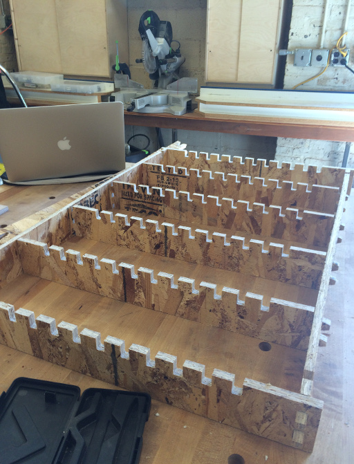
Half a box
A single horizontal face of the box press-fit together. Surprisingly tough and sturdy! A note on the design: for where I was constrained by the thickness of the stock (7/16th of an inch), I just assumed it would be 0.5 inches. This turned out to be quite tricky, one half of the stock (run #1) was greater than 0.5 inches in thickness, and the other half (run #2) the stock was less than 0.5 inches in thickness. This meant that the bottom of the box press-fit together snuggly, whereas the top was pretty loose. For the dimensions I did have control over, I made a tapered design so I could be flexible and just hammer things together. It turns out that the machine cut pretty much exactly how I designed, meaning my conservative spacing (leaning towards more space) made it so the pressfit was more on the loose side (snug but not significantly compressed). In the future if I design I might include the tapered design but keep it intentionally tight. This would make for a solid compressive fit that would hold things together nicely.
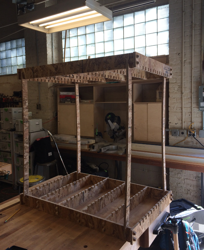
2 halves of a box
A completed box! Definitely needed more support on the vertical side, it was pretty wobbly. But the horizontal faces themselves were quite sturdy. Overall I was quite happy with how it turned out! The pressfit working without issue was a big help.
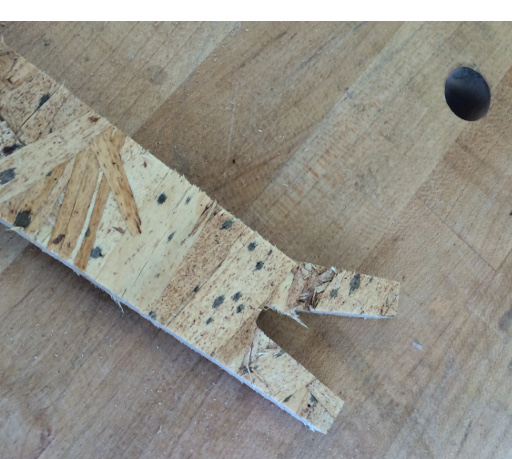
A stereotypical structural failure in the vertical beam
However, when I tried to move the box some of the mechanical design flaws became apparent. The lack of strength in the vertical axis led to the identical breakage of 3/4 of the "vertical beams". Luckily I had 4 extra from the 2nd run, but this event helped drive home the lesson of thinking about the mechanical and structural characteristics of a design a bit more closely.
Overall a very interesting week! Barring some frustration with MasterCam, this was a very enjoyable exercise. Quite remarkable to go from a digital design to an actual box sitting on a table in the span of a few days! Looking forward to applying these skills to make some big things in the future. Hopefully I'll be able to figure out MasterCam and the Onsrud again without too many issues.
Design files for posterity: