
Eagle schematic of the modded "hello FTDI" board
This week I had a pretty clear idea of how I wanted to mod the "hello FTDI". LEDs on data lines are always fun, as they flash when data is being transfered. Power indicator LEDs are also good, as they can help you diagnose problems with the board. These mods are something I had tried successfully with my FabISP, so this week I was a little more slapdash with it, but as we'll see that led to a design flaw. Other components on the board: the button switch pulling the reset line low when pressed, thereby reseting the microcontroller. I also made an extraneous addition to the board: I have the CKOUT (clock out) pin on the microcontroller attached to the drain of a N-mosfet, while the gate of the N-mosfet is being driven by another microcontroller pin. The source of the mosfet goes off onto a resistor, and what I plan will be an antenna. The point is this: I'm quite interested in radio and digital communications, but have never built my own RF circuits. I thought this board could be My Very Own Morse Code Transmitter®. By either blocking or passing the 20MHz clock signal from the microcontroller to an antenna, I could make a simple On-off keying transmitter at 20MHz. Basically my understanding of radio and electronics consists of: there are periodic signals, and there is an antenna involved. Beyond that, I have no idea what I'm doing, or how to make a proper antenna (impedance matching etc), but hopefully it'll work enough that I can get some data out of it at a few feet. That would be neat! As an aside, I'm pretty sure that using a square wave (as comes out of the clock) for the RF carrier wave is a bad idea™, as this will cause a lot of harmonic "spurious" emission as square waves are a poor imitation of sine waves. Technically speaking I think to use this part of the spectrum (20MHz) you should be a Amateur radio operator. I happen to have gotten my Amateur radio certification in highschool, but have no idea if that certification is qualified for this frequency or what. I suppose just keep the power low and it'll probably be okay.
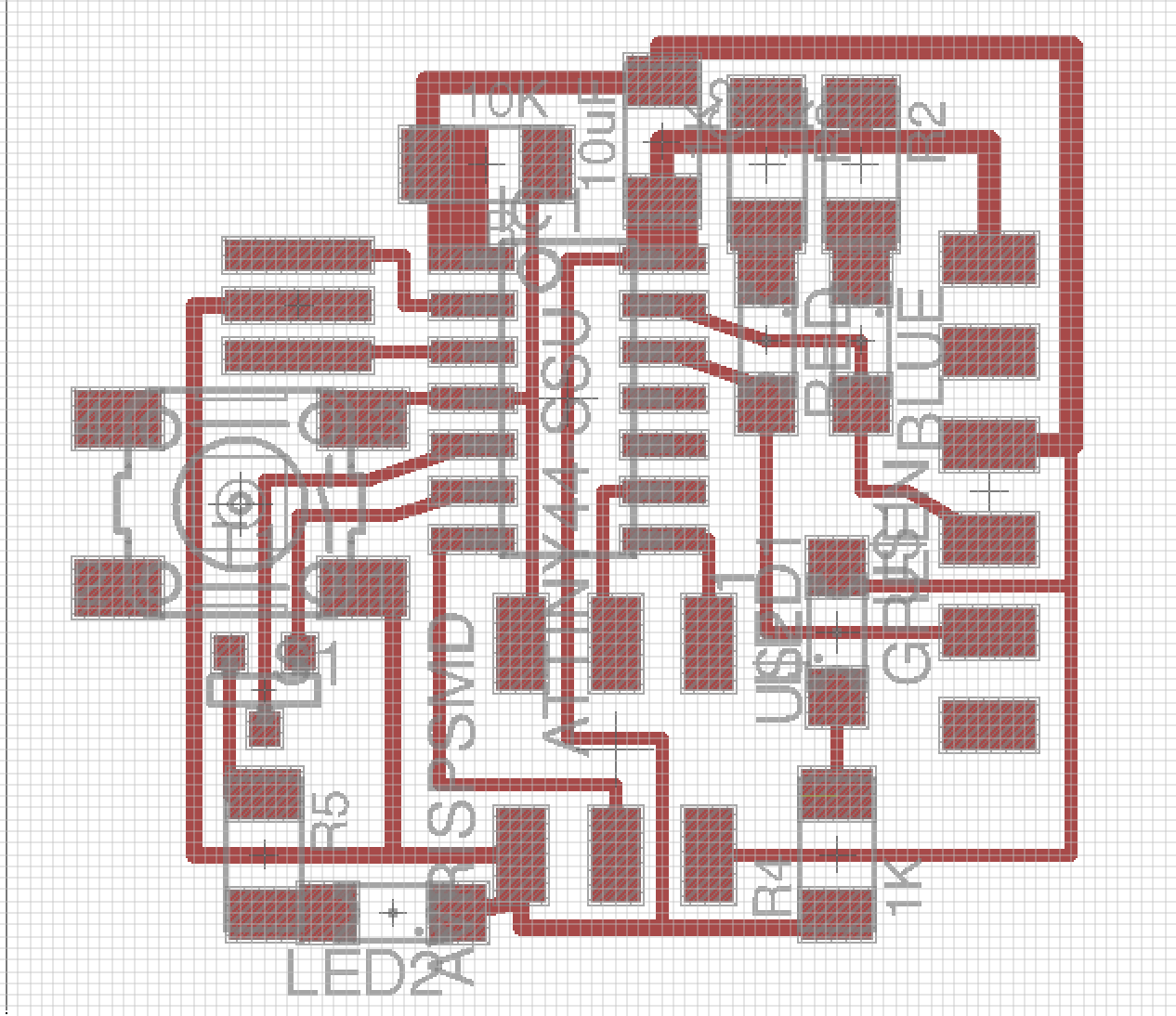
The PCB layout from Eagle
I think for the PCB layout side of things, I pushed it a bit too small. Looking back it is definitely hard to figure out what is going on. Overall I largely stuck with Neil's layout, and then added the additional components off to the side. I did add some beefier traces for the power lines (5V and GND).
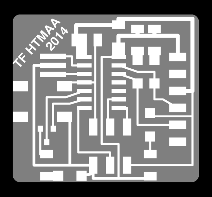
PNG cutouts used for Fab Modules and the Modela
Here is a overlay showing what the PNGs look like. The PNGs were exported from Eagle by viewing the right layers using "display none; display top" and "display none; display milling" commands. PNGs were exported at 2400 dpi (which I believe is the maximum Eagle will export at). I added the signature to the top/trace PNG with GIMP, and curved the corners of the milling layer in Inkscape. How to curving the corners deserves a little aside: First, when you import the PNG into Inkscape, the dimensions are all screwed up (way too big). Look at what the physical (millimeter) dimensions should be for the PNG in GIMP, and then reset the document properties in Inkscape to exactly those dimensions. Scale the embedded Inkscape bitmap proportionally turning on snap to page boarders, aligning the a corner to a page corner, and scaling proportionally by dragging a corner arrow while holding control. Then, you have a correctly sized version of the PNG in Inkscape. Turn the bitmap into an Inkscape path by using the "Trace bitmap" tool. Next, I added some nodes to the box geometry, 2 nodes per corner 1mm X or Y offset from the corner. Then I deleted the corner thereby making the corners little 45˚ angles. By selecting both corners, hitting "Make selected segments curve", and then "Make selected segmenents smooth", it gives you a nice curve between the two points without affecting anything else. In the end it was just a small aesthetic change to the standard rectangle produced by Eagle.
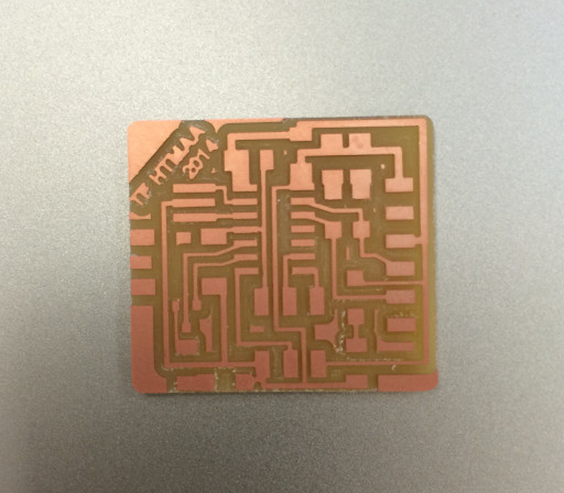
Sucessful Modela milling
A successful Modela mill! Only change is making the 1/64th endmill offset a little smaller (0.35) which helps with toolpath generation for small trace widths.
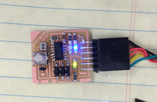
Powered up and operating/h6>
All soldered together and working fine! With one exception, herein lies the design flaw mentioned earlier: The green LED you see is the power LED, whereas the blue LED is only supposed to be active when data is being transfered. It turns out, that the UART serial connection is idle high, when I expected it would be idle low. This means the LED is always on, though it will rapidly blink (perhaps indiscernable) on serial data transfer. A fix for this situation: Flip the LEDs around, and connect them to 5V instead of GND. This would make it so current flows when the trace is non high, aka when it is not idle and is actively transfering data. Wouldn't be very hard to redo the design in Eagle and change some traces around, but without a new board don't think this can be fixed.
Looking forward to two weeks from now when we learn how to program them!