This week we learned about input sensors. Our assignment was to design, mill, stuff & program a board that uses one of the sensors.
I’ve decided to use the thermistor.
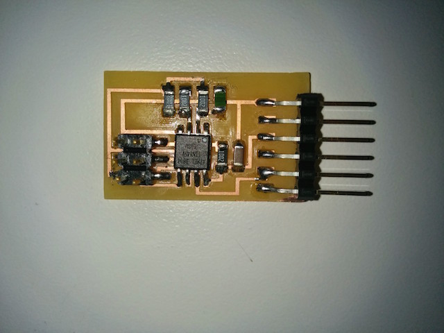
The first board I created, as a baseline, was an exact copy Neil’s hello.temp.45 board.
I used Neil’s code as is and got the expected response from the python script.
As an exercise I also created a Node.js app that relays the serial input to a webclient that handles the conversion of the serial input into actual temperature and displays it. The code is available at https://github.com/tomerweller/serial-to-socketio
For my own board design, I added an rgb LED and changed the chip to any ATtiny44.
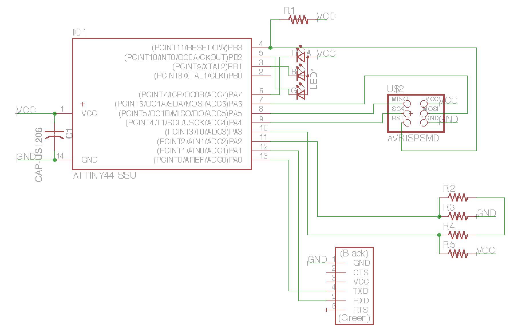
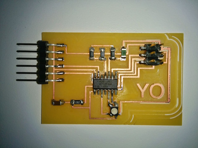
Due to lack of ability to communicate with the programmer I replaced the ATtiny44 chip which solved the issue. (The board photo was taken after the replacement)
To program the chip I altered neil’s code: hello.temp.44.make, hello.temp.44.c
Let’s review the changes in code:
diff hello.temp.45.c hello.temp.44.c29,31c29,31
< #define serial_port PORTB
< #define serial_direction DDRB
< #define serial_pin_out (1 << PB2)
---
> #define serial_port PORTA
> #define serial_direction DDRA
> #define serial_pin_out (1 << PA1)
114,116c114,115
< ADMUX = (0 << REFS2) | (0 << REFS1) | (0 << REFS0) // VCC ref
< | (0 << ADLAR) // right adjust
< | (0 << MUX3) | (1 << MUX2) | (1 << MUX1) | (1 << MUX0); // 20(PB4-PB3)
---
> ADMUX = (0 << REFS1) | (0 << REFS0) // VCC ref
> | (1 << MUX5) | (1 << MUX4) | (0 << MUX3) | (0 << MUX2) | (0 << MUX1) | (1 << MUX0); // 20(PA3-PA2)
The serial port changes are trivial.
The ADMUX is the selection register for the analog to digitial converter. I had to change this to select my inputs: ADC3 (PA3) as positive and ADC2 (PA2) as negative wigth a 20x gain. A quick look at t44 spec (section 16.3) informed me on which bits to turn on.
The programming worked but there is some problem with the conversion. This is the result: (debugging in progress)