This week was about output devices. Our assignment was to design, mill, stuff & program a board that uses an output device.
As preperation for my final project I’ve decided to build a led array board that’s controlled via a web interface.
WARNING: THIS BOARD HAD A DESIGN FLAW IN IT, DO NOT REPLICATE
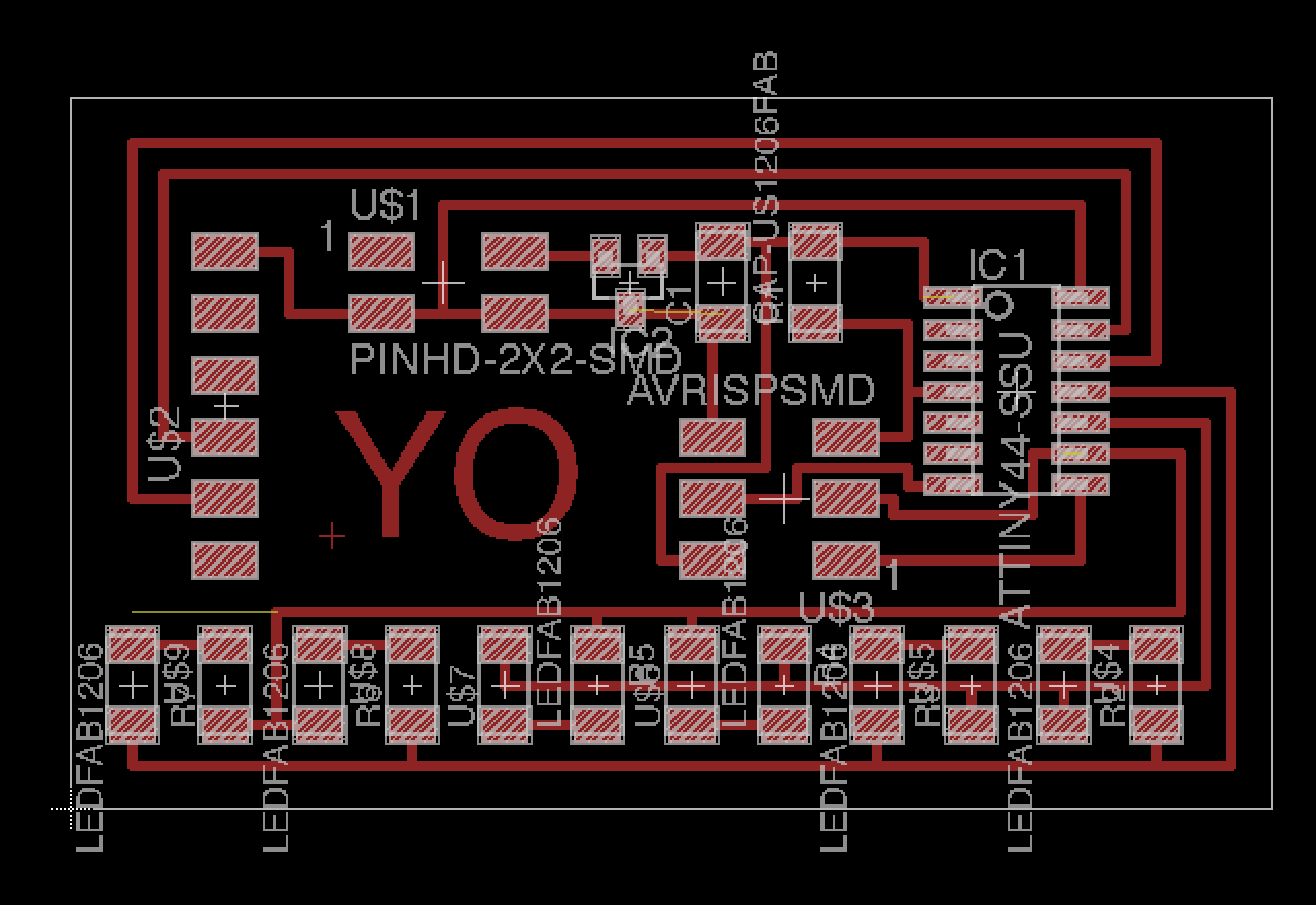
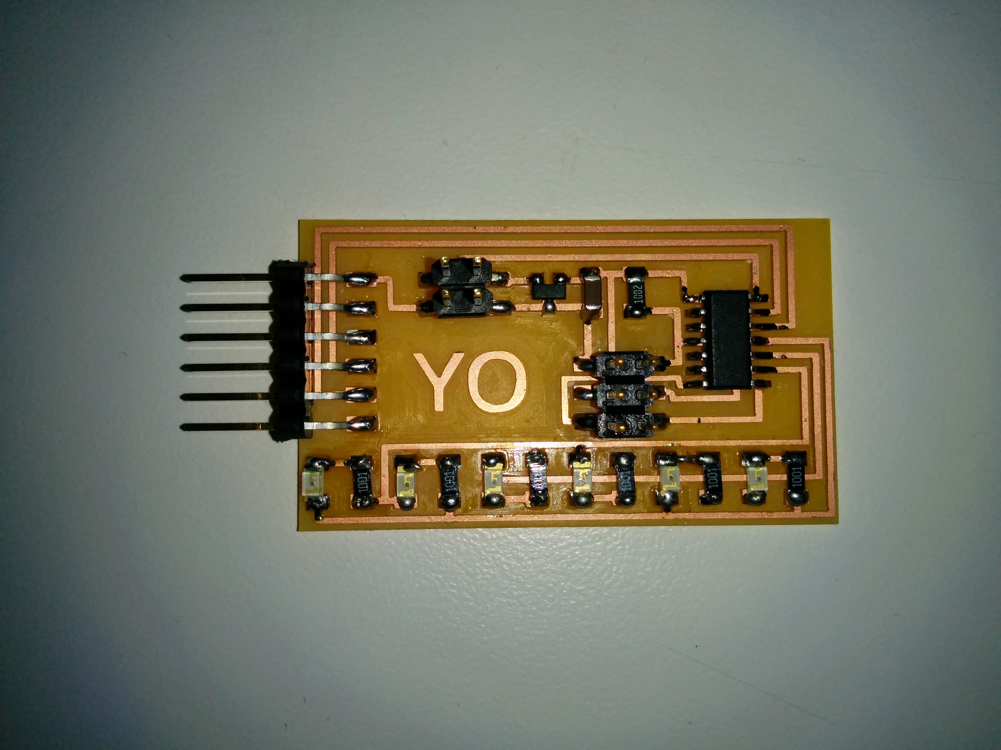
Board
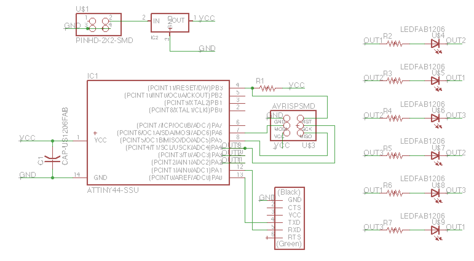
 Note: in retrospective I did not need need a resistor for each LED. I could have used just 3 resistors on the output pins.
Programming
 I borrowed from Neil’s hello.ftdi.44.echo code code and hello.aray.44 code. The main() function:
int main(void) {
   static char chr;

   // set clock divider to /1
   CLKPR = (1 << CLKPCE);
   CLKPR = (0 << CLKPS3) | (0 << CLKPS2) | (0 << CLKPS1) | (0 << CLKPS0);

   // initialize output pins
   set(serial_port, serial_pin_out);
   output(serial_direction, serial_pin_out);

   // main loop
   while (1) {
      get_char(&serial_pins, serial_pin_in, &chr);
      switch(chr){
         case 'a': flash(B,A, led_pressed_delay); break;
         case 'b': flash(A,B, led_pressed_delay); break;
         case 'c': flash(B,C, led_pressed_delay); break;
         case 'd': flash(C,B, led_pressed_delay); break;
         case 'e': flash(C,A, led_pressed_delay); break;
         case 'f': flash(A,C, led_pressed_delay); break;
      }
      put_char(&serial_port, serial_pin_out, chr);
   }
}
full code - hello.array.serial.44.c
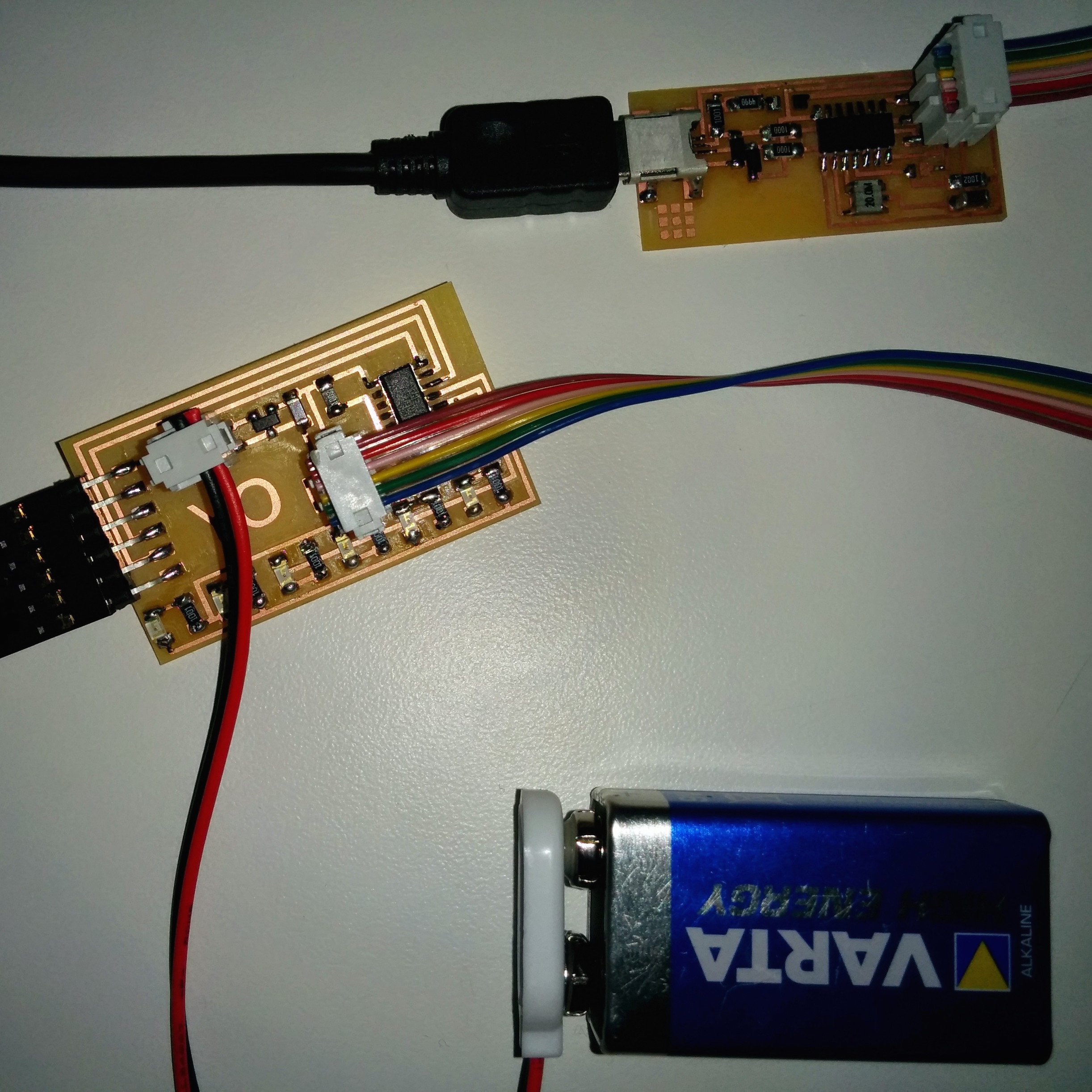
I improved my last week’s serial-to-socketio relay example so that I can also write to the serial port. The full code is at https://github.com/tomerweller/serial-to-socketio
Generally, it works. However, It’s visible that some LEDs that are not supposed to light up have some current flowing through them. Needs further debugging.