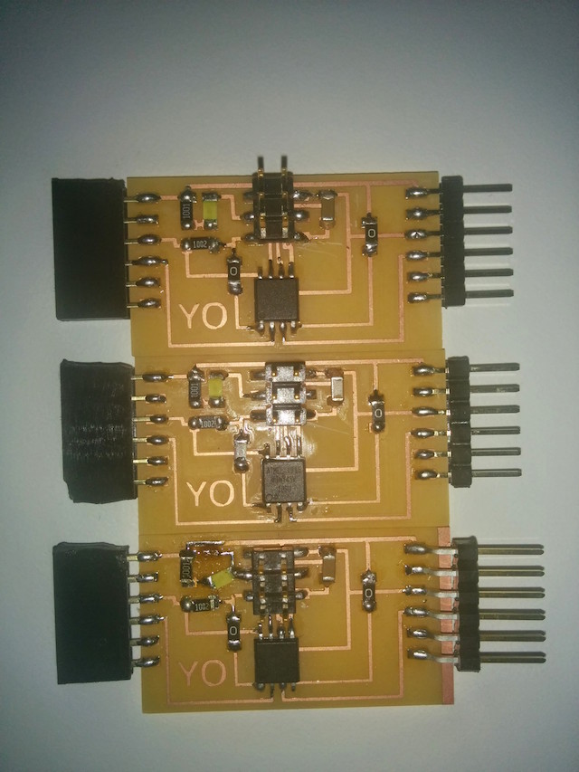
This week was about output devices. Our assignment was to design, mill, stuff & program several boards that communicate with one another. I built a “Binarizer” : an array of boards that represent a binary number, each board represents a single digit.
All these boards are identical both in hardware and in software. The more boards you have - the bigger the number you can display. (up to 8 in this case but can easily support more).
The boards communicate one-way with the standard RS-232 (serial) protocol. Logic per board is simple:
- Receive a byte.
- Display least significant bit of the byte (0 => LED off, 1 => LED on).
- Perform a one digit right bit shift on the byte (b » 1)
- Send byte to next board.
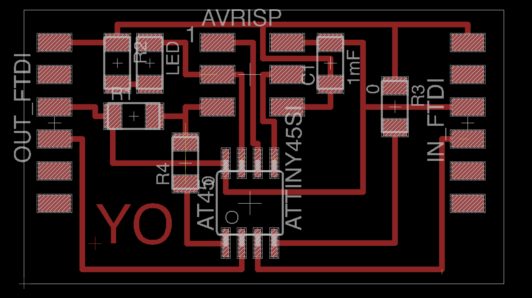
Board
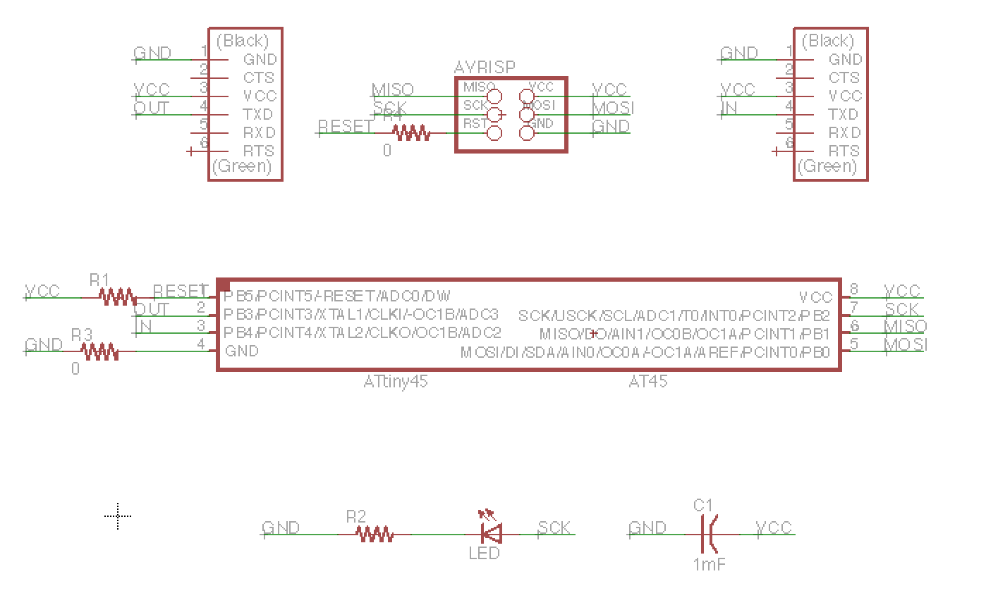
Programming
int main (void) {

   static char chr;
   static uint8_t i;

   MCUCR |= _BV(PUD);

   // set clock divider to /1
   CLKPR = (1 << CLKPCE);
   CLKPR = (0 << CLKPS3) | (0 << CLKPS2) | (0 << CLKPS1) | (0 << CLKPS0);

   // initialize output pins
   set(serial_port, serial_pin_out);
   output(serial_direction, serial_pin_out);
   output(led_direction, led_pin_out);

   // main loop
   while (1) {
      get_char(&serial_pins, serial_pin_in, &chr);
      i = (uint8_t)chr;
      if ((i%2) == 1) {
         set(led_port, led_pin_out);
      } else {
         clear(led_port, led_pin_out);
      }
      put_char(&serial_port, serial_pin_out, chr >> 1);
   }

}To start the sequence I send a byte over the ftdi to the first board with a node.js app : https://github.com/tomerweller/serial-to-socketio
Lessons learned:
- VERIFY YOUR TRACES. Triple check that your toolpath doesn’t merge any traces and that the milled board is identical to design. My toolpath was wrong which caused my 3 boards to malfunction. Fortunately, It was easy to fix with an exacto knife.
- SECURE DEBUG OPTIONS. Beacause I only had one serial out and it was used for communication between boards I had no way to print logs. This was a disaster and cost me several hours of guessing what’s wrong.