Electronics Design
Printed Circuit Board Design in Eagle
(5V - Vd)/Im
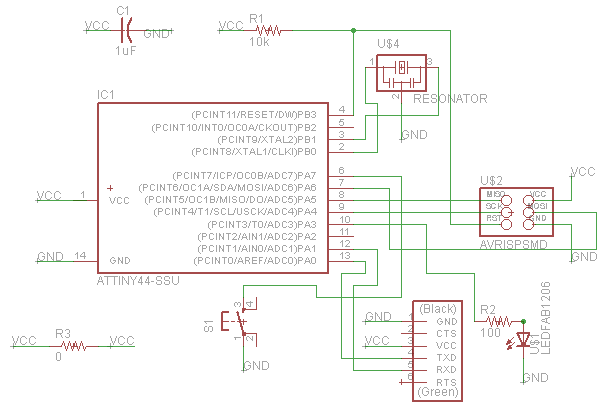
in order to keep the current through the LED at less than Im during operation.In drawing the board, using the "net" feature to connect repeated, common terminals such as VCC and GND was very convenient. This involves typing "net," drawing the connection to a particular terminal, then using "name" to rename the net to a common name, e.g. VCC. The program will then ask whether you actually want the new connection to be connected to every other instance of VCC, to which you answer in the affirmative. Finally, it is helpful to label your net so you know what is connected to what.
When using "net" or "wire," to connect terminals of components that you put on the board from existing library files, sometimes I was not careful with where I clicked and did not produce a connection that Eagle recognized. The way to make sure the connection has been made is to go into the board view and check that there is a new, unrouted yellow line.
On the schematic I decided to put one zero-Ohm resistor to help me get my VCC lines everywhere I needed it to go. Otherwise it became a nightmare trying to avoid crossing wires and also keeping enough clearance between traces.

