Electronics Production
This week the assignment was to make a FabISP.
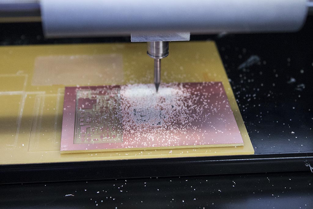
The first step was to mill the connections needed to make the circuit board. We used a 1/64" diameter endmill to removed copper from an FR1 printed circuit board. The remaining copper traces make up the structure of the circuit board. A secondary contour cutting pass with a 1/32" endmill releases the board from the stock.
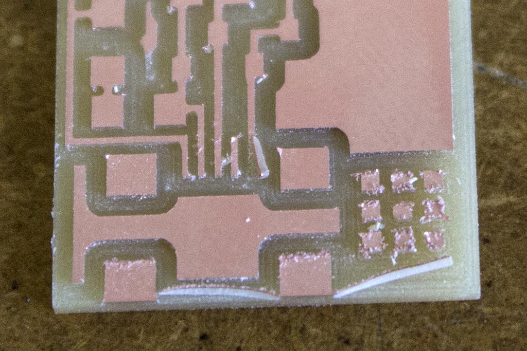
That all sounds quite straightforward in theory, but in practice it took a few attempts to get a usable board. The first problem (pictured above) was caused by a combination of a dull endmill + a slightly out of level sacrifical board below the material. This resulted in a lot of fuzzy edges + a couple spots where the copper actually delaminated from the board. Not ideal for completing a circuit.
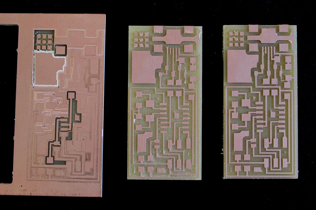
Bad. Less bad. Good. On my second attempt (pictured at left), the endmill broke - confirming the suspicion that it was pretty worn out. The first attempt is in the center of the image - it didn't come out nearly as cleanly as my third attempt (pictured at right).
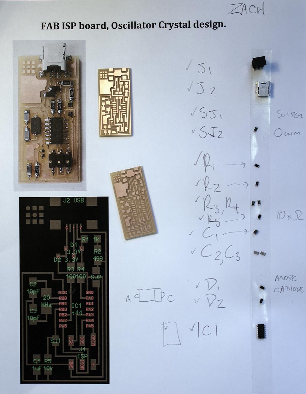
Rob brilliantly suggested that I adhere all of the components needed for the board on a printout of the board. This helped to keep all of the tiny parts organized and saved me from trying to repeatedly identify each component.
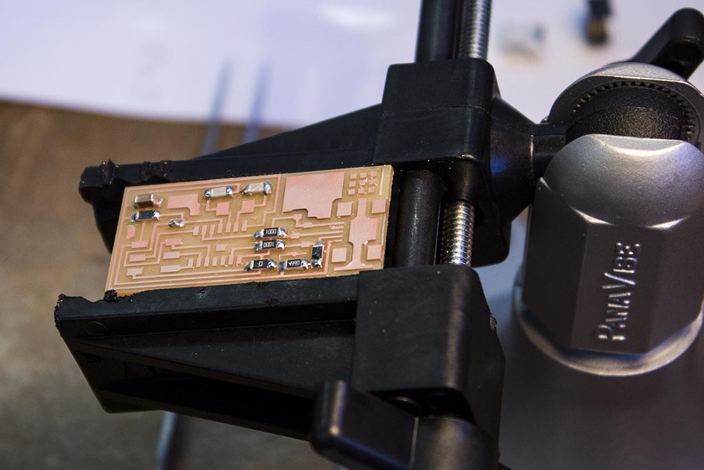
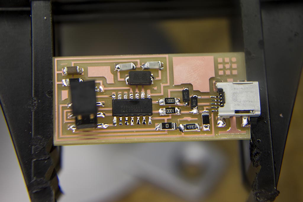
The board in progress. I tried to be super systematic in the order I soldered the components to the board. I started with the small stuff that wouldn't get in the way later on- resistors, capacitors, etc. I found that the orientation of the component, and way in which I was able to comfortably hold the iron + tweezers played a big role in the order that I soldered things.