Electronics Design
This week the assignment was to redraw the echo hello-world PCB. The board needed to have an LED and a switch. Things went pretty smoothly, aside from a couple false starts when learning Eagle.
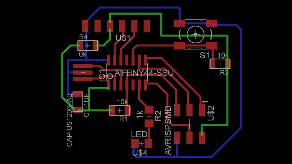
An early version of my board. Initially, I was having trouble keeping the unrouted traces straight so I used color to track complicated paths like the ground (shown here in blue) and VCC (in green). I eventually realized that using the "route" command rather than the "wire" command highlighted where my traces needed to go. This made things a LOT easier to keep straight.
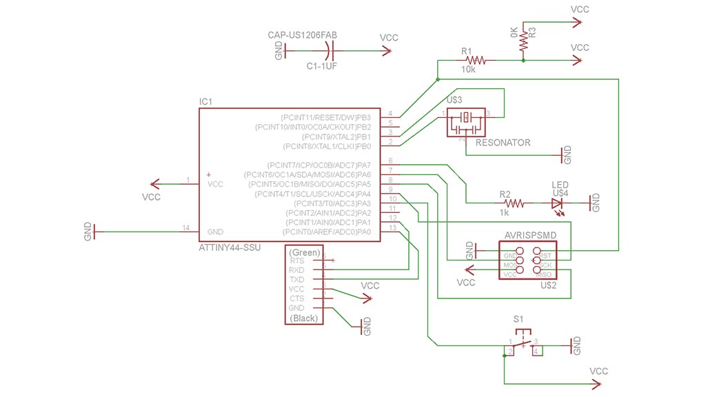
The final schematic of my board. I ended up having to use a 0 ohm resistor as a bridge to connect my traces. I'd like to try rerouting everything from the beginning again to see if I could have better results starting with ground + vcc rather than leaving them for the end.
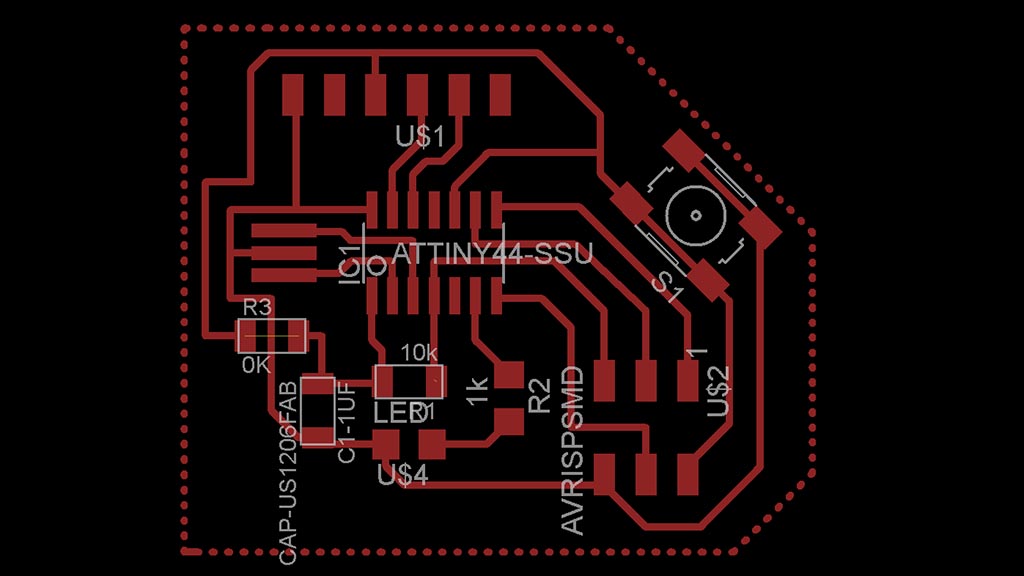
The final board design. I used a wire width of .016 for my traces.
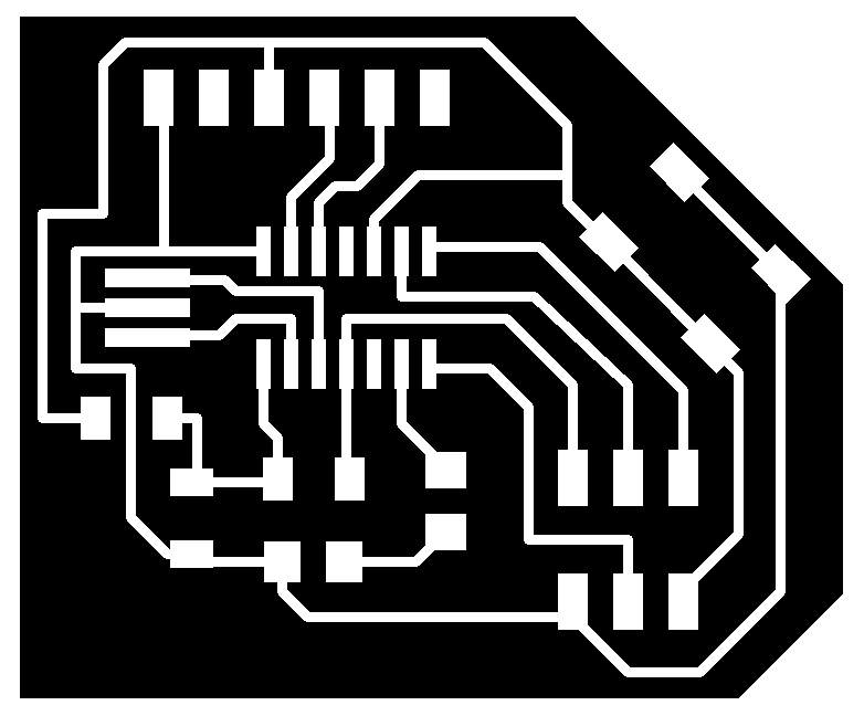
Final traces.

Final outline.
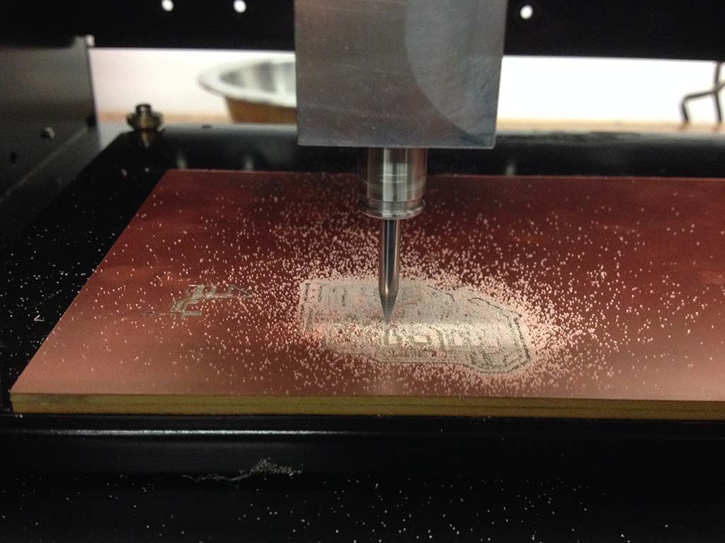
Milling the board. I broke a new 1/64" bit on the first try. Though I used the default settings in the fab module, my guess is that my cut depth was slightly too deep. I reduced the cut depth and milled again.
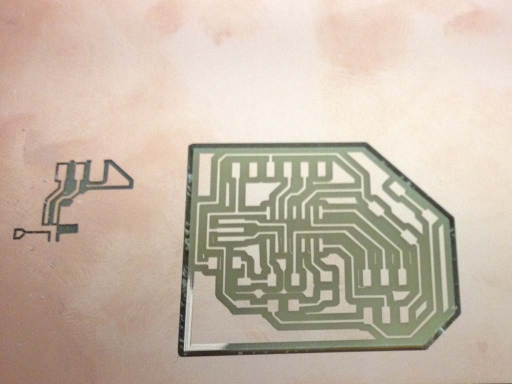
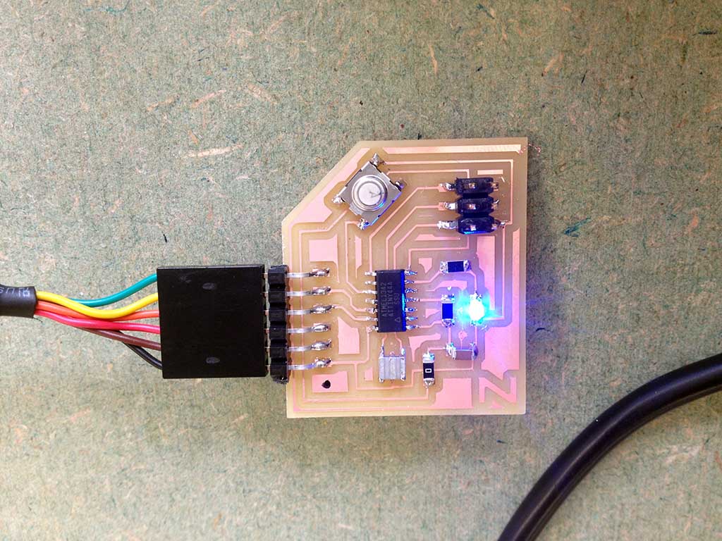
The final board on the right + my first attempt at left.
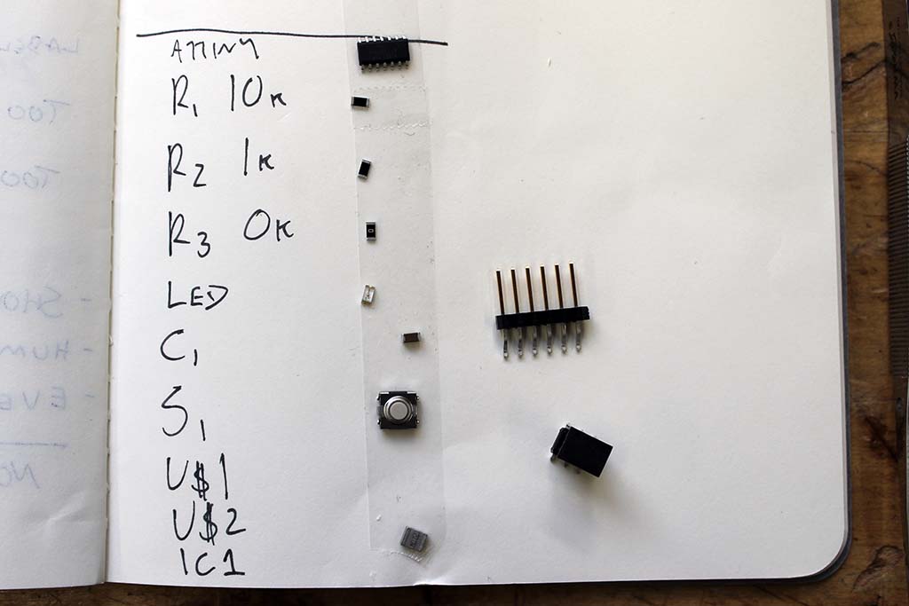
I didn't print out a materials list or photo of my board, but made a quick and dirty version of the same thing in my sketchbook.
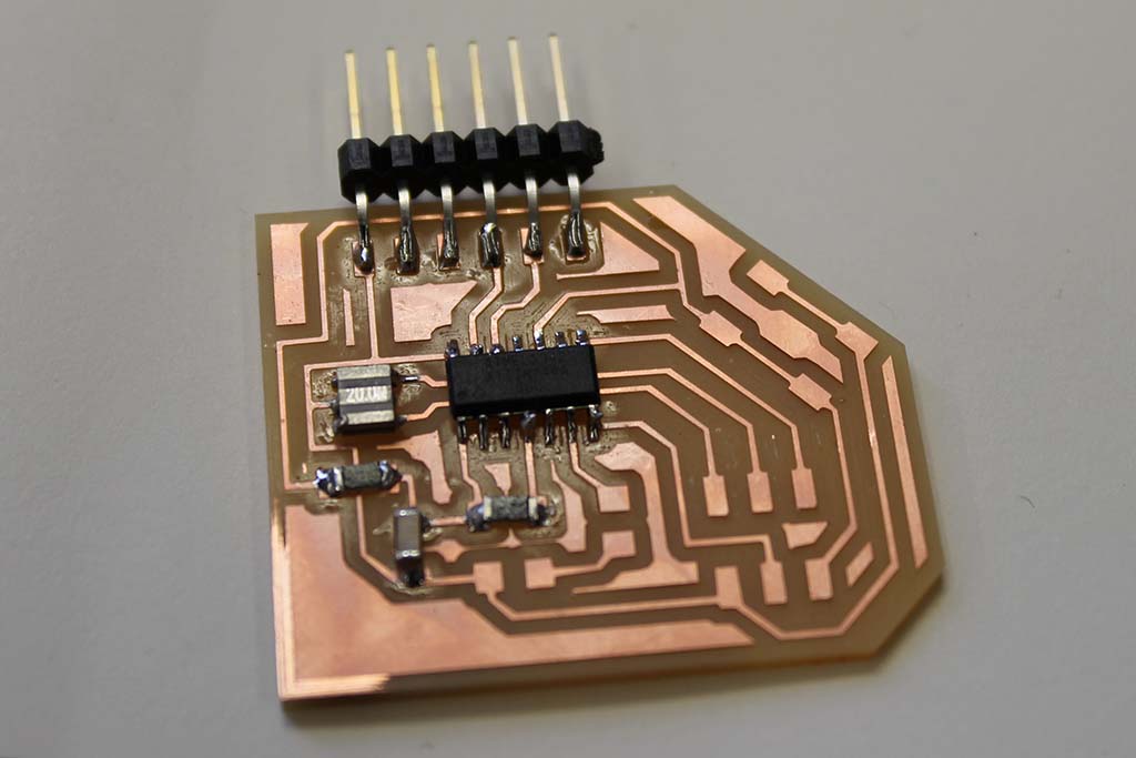
The board about halfway stuffed.
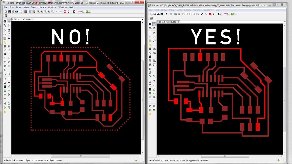
Once I was ready to test my board, Rob (thankfully) noticed that I'd made a pretty serious error in my schematic design. My switch was connected to my 5V VCC! Needless to say, that wasn't going to work. I made a couple quick edits in Eagle - the VCC trace is highlighted in each image. Reexported, remilled, restuffed... Good practice for the board production process if nothing else!
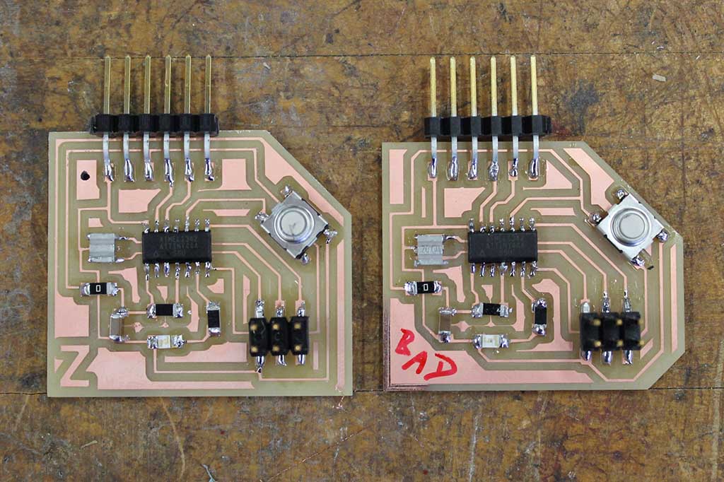
The incorrectly routed board at right, the correct one at left.