Final Project
Here it is. I decided to make a prototype for a facade shading system using shape memory alloy wire. While it is challenging to control precisely it does have the advantage of being more or less immune to fatigue-based failures (no moving parts...) and is completely silent when actuating. I had been working with shape memory since output devices week and got interested in how easily one could control a relatively large number of wires with minimal means.
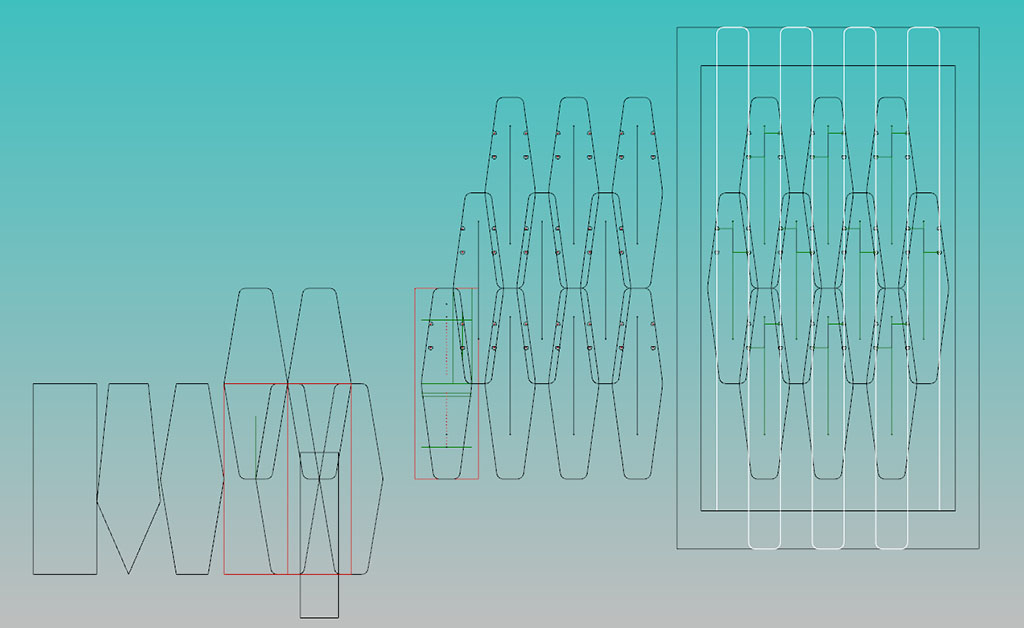
I designed my project components in Rhino. Once I was done designing, I extracted the geometry I needed for lasercutting the plastic fins + CNC milling the support frame from my digital model.
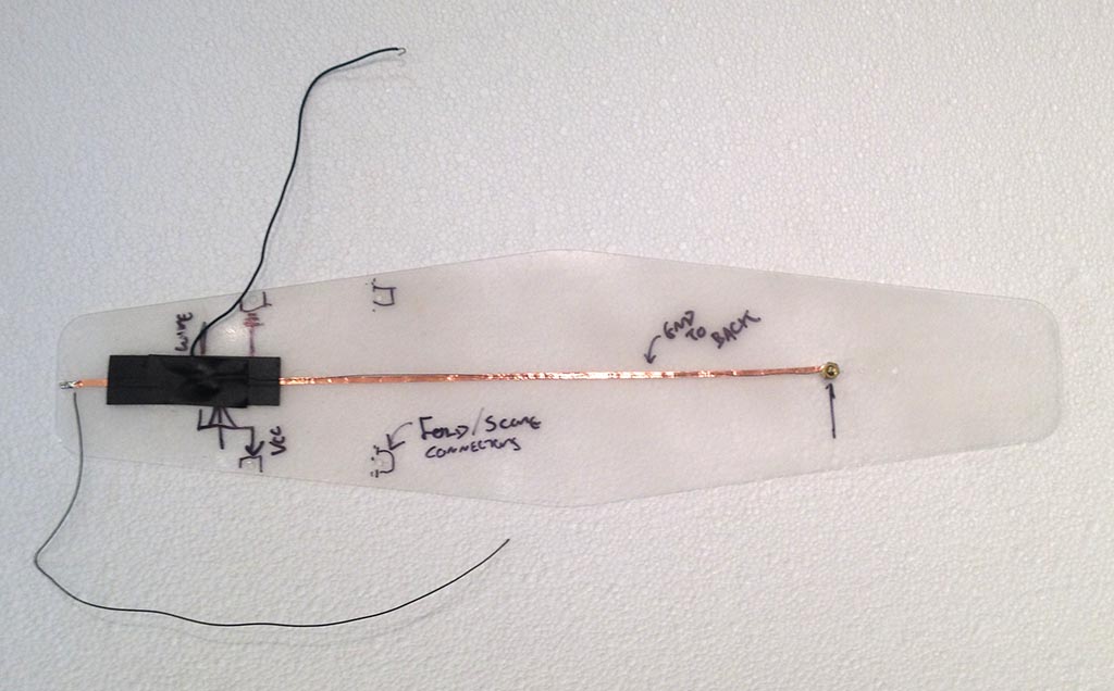
Before I went ahead and cut EVERYTHING, I cut one test fin out of .020" thick PETG (it's more flexible + less brittle than acrylic). I used this test piece to confirm placment of my SMA wire, test the conductivity of vinyl cut copper traces, as well as develop a strategy for attaching shape memory wire to the fin and the fin to the steel cable. This was really helpful, as I ended up making a number of small changes to the part geometry to improve the assembly process and control the motion of the SMA wire. I also used this piece to test surface finishes - I wasn't sure if sandblasting or hand sanding would produce the visual effect I was looking for.
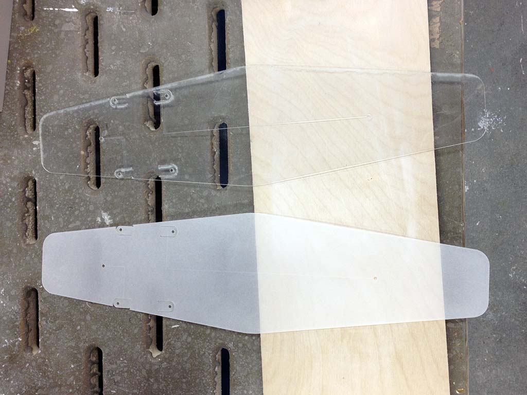
I ended up using a random orbital sander w/ 120 grit sandpaper to increase the opacity of my fins. It was pretty easy to get a uniform finish on both sides.
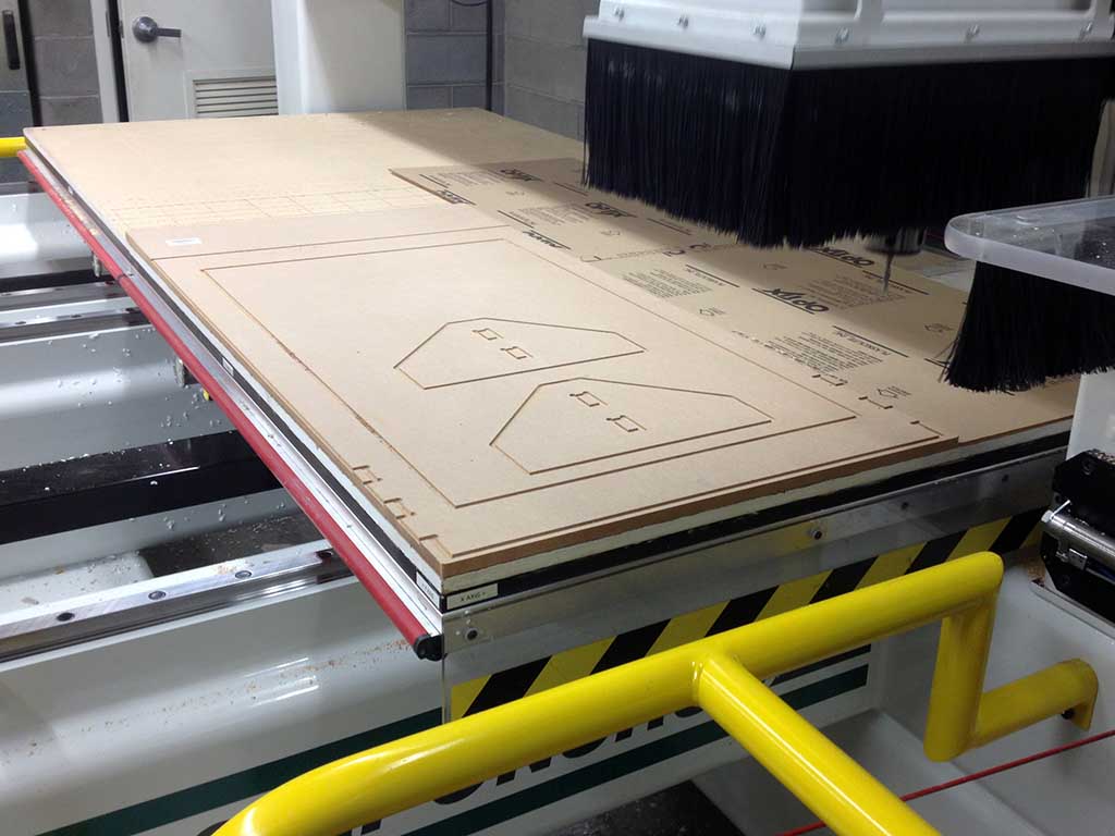
I knew I wanted to have a tensile support structure for my fins as this would give my surface the lightest appearance possible. I used (2) layers of 1/2" x 2' x 4' MDF to create a frame big enough to hold 11 fins. In order to get a clean edge finish, and reduce post-processing time as much as possible, I first cut all of my contours with a 1/4" downcut endmill at about 1/8" cut depth before doing the bulk of my contour cutting with a 1/4" upcut endmill. The above photo was taken at the end of the 1/4" downcut toolpath.
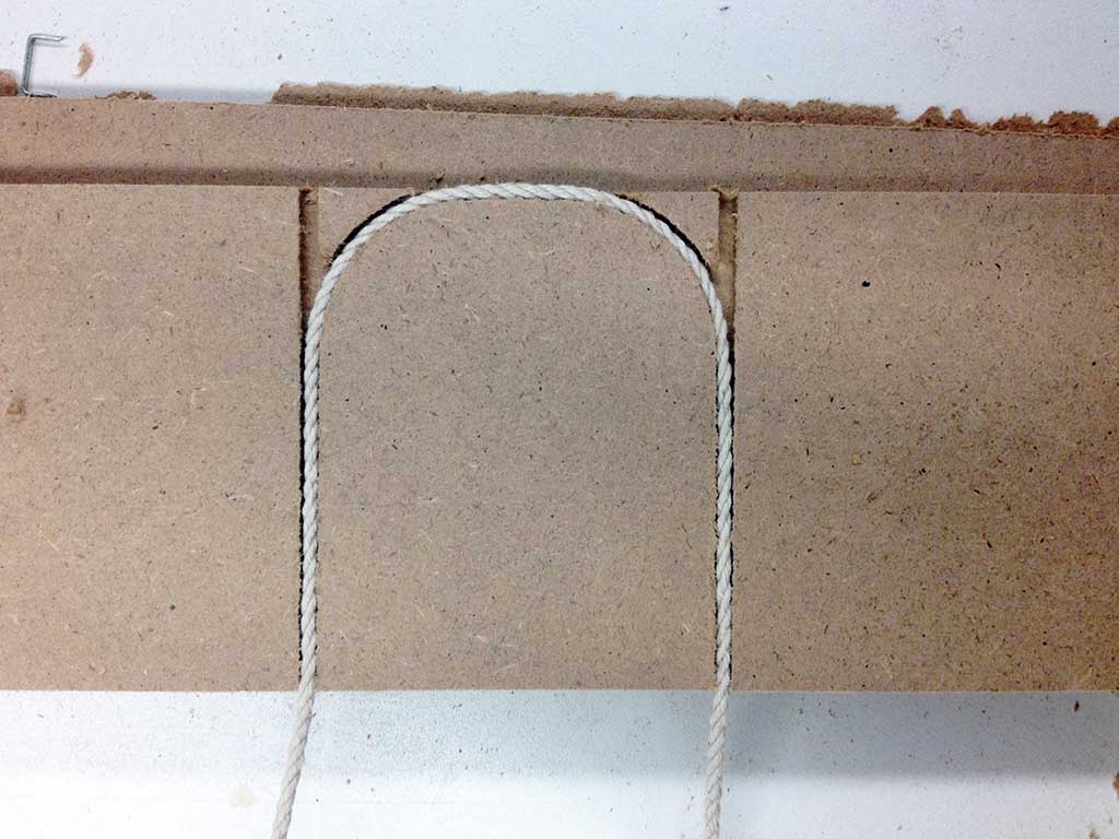
I cut traces at the inside of one half of the frame to route a single length of 1/16" braided steel cable through the entire frame. The filleted corners helped the wire move more freely through the frame and thus equalize tension along its length. I ended up drilling out the small triangular shapes between the two contours - the braided wire was almost impossible to route with them in place!
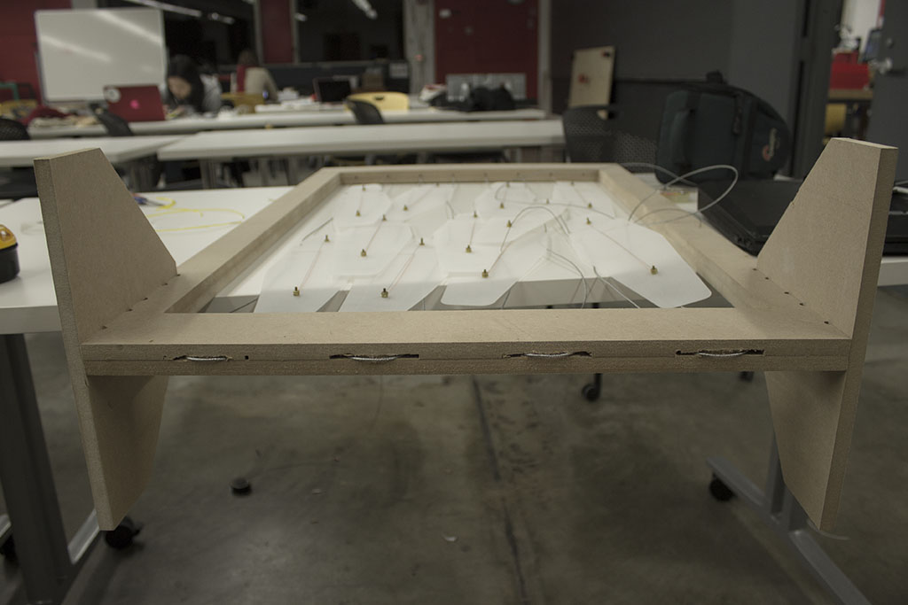
A view of my project during assembly. It took a few hours to develop a good workflow for routing the wire through everything correctly.
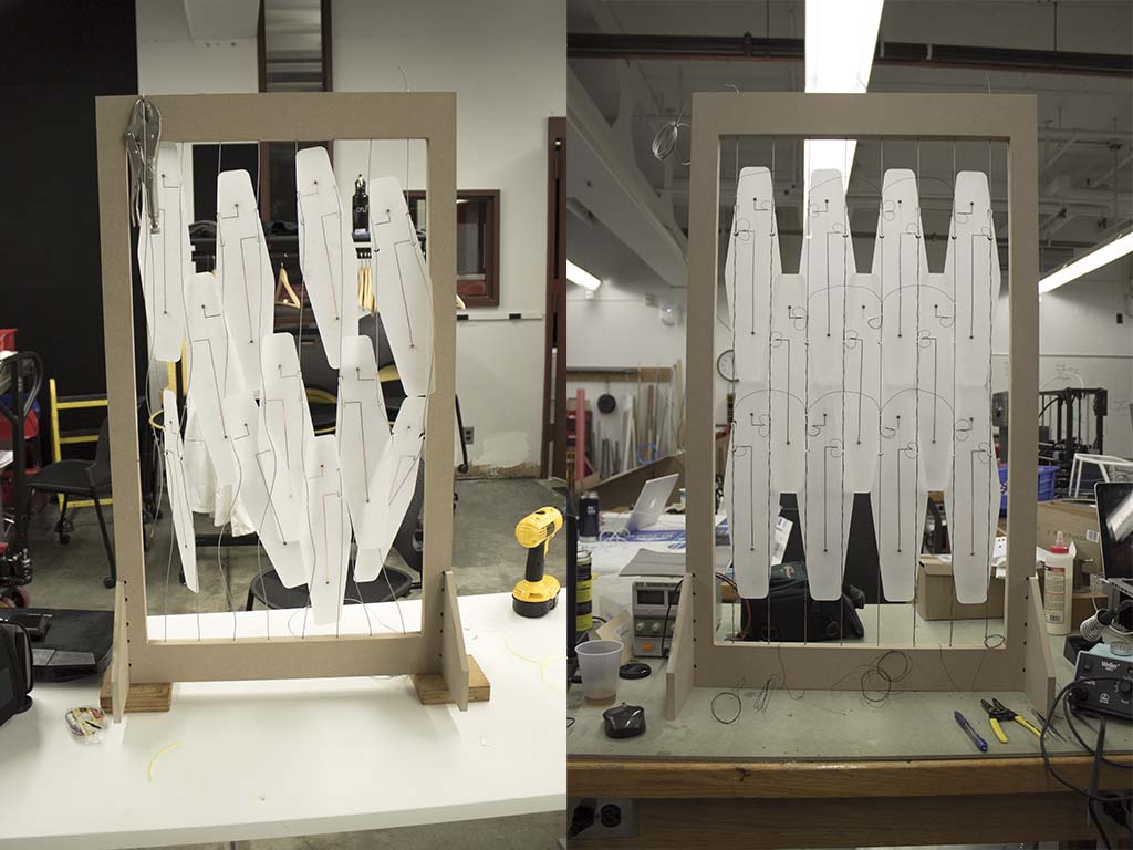
My project pre and post wire tensioning and fin adjusting.
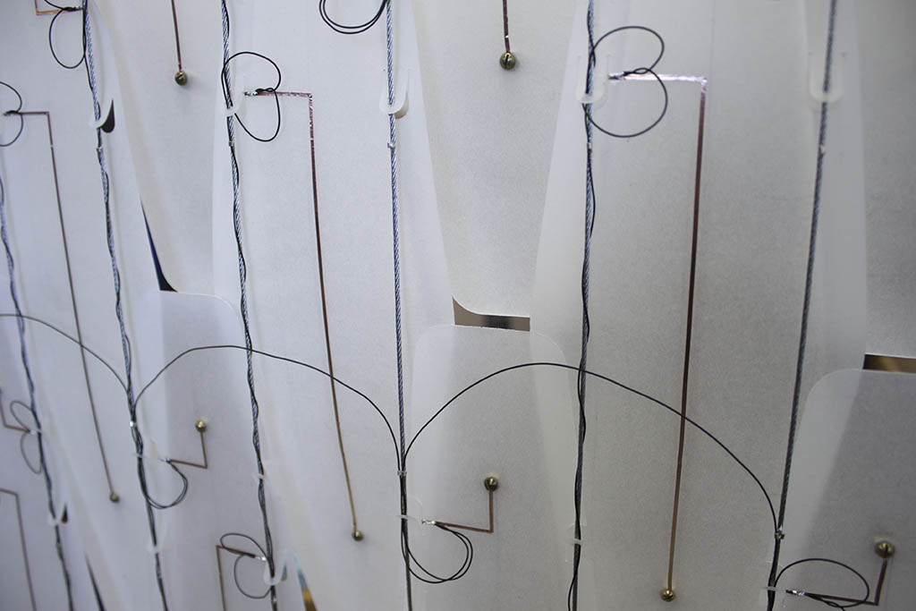
A detail shot of the wiring. The black wire is 28 gauge insulated wire we had in the lab. The wire running in a series of upside-down U shapes is connected to V+ on my board. Each of the 3 rows is controlled by a single p-MOSFET. The wires making the smaller capital B shapes are are connected to a single n-MOSFET per row. The SMA wire is attached on the other side of the fins by the brass screws. I'm using the brass screws as vias to connect my vinyl-cut copper traces to my SMA wire, and also as a means of adjusting the tension of each wire.
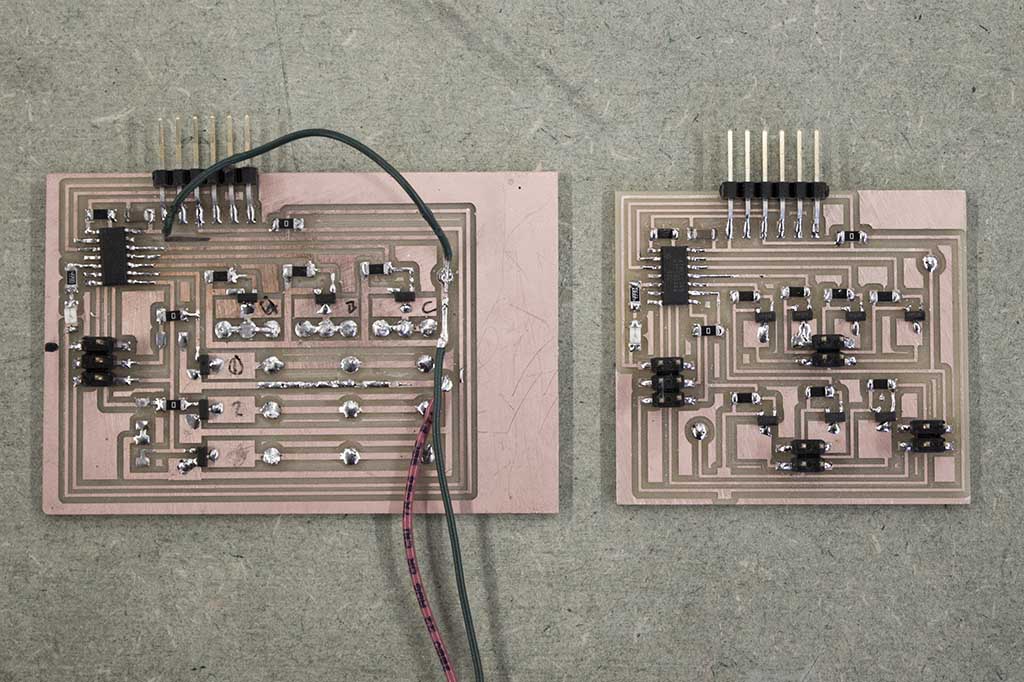
I made some revisions to the board I designed last week (at left) to add another n-MOSFET and clean up the connections between the SMA and the board. Now power and connection to each SMA row + column are accomplished with 2x2 pin headers. There are still pins available for serial communication/data input for when I am able to add an input device.
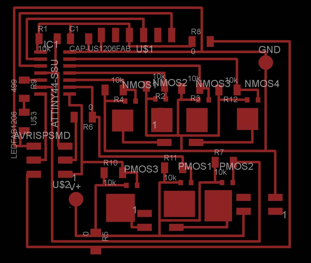
A view of the components I used on my board. The design of this board was initially focused on a question of whether or not one could charliplex things other than LEDs. The nice thing about charlieplexing is that you can control N*(N-1) objects with only N pins - eg. 7 pins control 7*6=42 objects. Well, it turns out you can't do quite that well with MOSFETs, but it's still possible to be pretty economical. My board works as an array - it controls N*J objects with N+J pins (eg. 3+4=7 pins control 3*4=12 objects) - not bad for an ATtiny44! A huge thanks to Jean-François Duval for his help in figuring this out.
So here's how it works: I have an array of 12 lengths of SMA wire arranged in 3 rows and 4 columns. Each row is controlled by a high-side P-MOSFET and each column is controlled by a low-side N-MOSFET. There's nothing that prevents turning on multiple rows (P-MOSFETs)at a time so long as I only ground one column (N-MOSFET). To actuate the array, I can cycle through the columns at a duty cycle of 1/K - where K = number of columns (N-MOSFETS). Where an LED array relies on persistence of vision, my array relies on the thermal inertia of SMA wire.
Here are the files for the board and schematic.
You can find a simple "blink" sketch for the board here.
Project Stats
What does it do? Its a dynamic shading system actuated by an array of SMA wire.
Who's done what beforehand? Jie Qi has written an online tutorial about the basics of SMA control. Andy Payne made a mockup for a heat sensitive facade. Plenty of other architects have used SMA in interesting ways.
What did I design? What Processes were used? I designed a circuit in Eagle, a CNC milled MDF frame, PETG "fins", vinyl cut copper traces.
What materials were used, where did they come from and how much did they cost? All of the electronics were available in the Fab Lab Inventory. The SMA wire was from robotshop.com. It cost $27.50 for 5 meter roll. The PETG was from Altec Plastics in Boston. I fit all of my plastic components onto one $15.00 sheet of .020" thick PETG. The MDF, etc. was from Home Depot and cost about $25.00 total. The project grand total? About $65.00.
I cut traces at the inside of one half of the frame to route a single length of 1/16" braided steel cable through the entire frame. The filleted corners helped the wire move more freely through the frame and thus equalize tension along its length. I ended up drilling out the small triangular shapes between the two contours - the braided wire was almost impossible to route with them in place!
A view of my project during assembly. It took a few hours to develop a good workflow for routing the wire through everything correctly.
My project pre and post wire tensioning and fin adjusting.
A detail shot of the wiring. The black wire is 28 gauge insulated wire we had in the lab. The wire running in a series of upside-down U shapes is connected to V+ on my board. Each of the 3 rows is controlled by a single p-MOSFET. The wires making the smaller capital B shapes are are connected to a single n-MOSFET per row. The SMA wire is attached on the other side of the fins by the brass screws. I'm using the brass screws as vias to connect my vinyl-cut copper traces to my SMA wire, and also as a means of adjusting the tension of each wire.
I made some revisions to the board I designed last week (at left) to add another n-MOSFET and clean up the connections between the SMA and the board. Now power and connection to each SMA row + column are accomplished with 2x2 pin headers. There are still pins available for serial communication/data input for when I am able to add an input device.
A view of the components I used on my board. The design of this board was initially focused on a question of whether or not one could charliplex things other than LEDs. The nice thing about charlieplexing is that you can control N*(N-1) objects with only N pins - eg. 7 pins control 7*6=42 objects. Well, it turns out you can't do quite that well with MOSFETs, but it's still possible to be pretty economical. My board works as an array - it controls N*J objects with N+J pins (eg. 3+4=7 pins control 3*4=12 objects) - not bad for an ATtiny44! A huge thanks to Jean-François Duval for his help in figuring this out.
So here's how it works: I have an array of 12 lengths of SMA wire arranged in 3 rows and 4 columns. Each row is controlled by a high-side P-MOSFET and each column is controlled by a low-side N-MOSFET. There's nothing that prevents turning on multiple rows (P-MOSFETs)at a time so long as I only ground one column (N-MOSFET). To actuate the array, I can cycle through the columns at a duty cycle of 1/K - where K = number of columns (N-MOSFETS). Where an LED array relies on persistence of vision, my array relies on the thermal inertia of SMA wire.