We were given four kits of lead screws/ linear actuators which we can laser cut and assemble into any configuration that we desire (designed by Nadya Peek and James Coleman) . The key challenge was to use all four! We all agreed that we wanted to put a magnet at the end effector of the machine. This would allow us to make something that could move magnetic objects in a controlled way. One application could be for playing chess. With an automatic chess-player as the goal, this set the direction for the programmers.
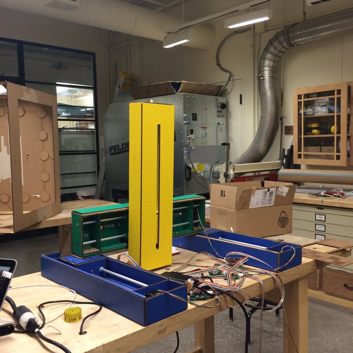
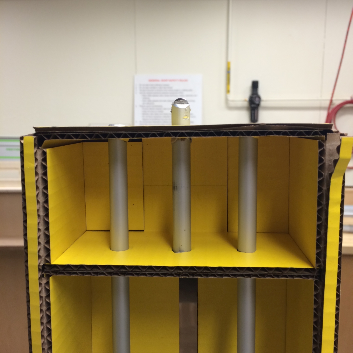
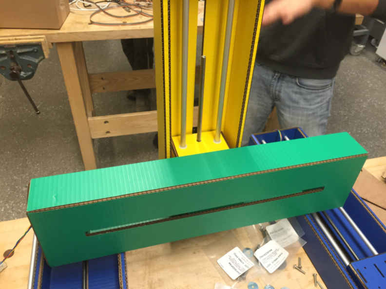
We started constructing the linear actuators by laser cutting the cardboard pieces from the files provided by Nadya and James, press-fitting them together, and then adding the motor and actuators. The X-Direction is controlled by the blue actuators, the y-direction by the green, and the z-drive is yellow. Pictures of this can be seen below:
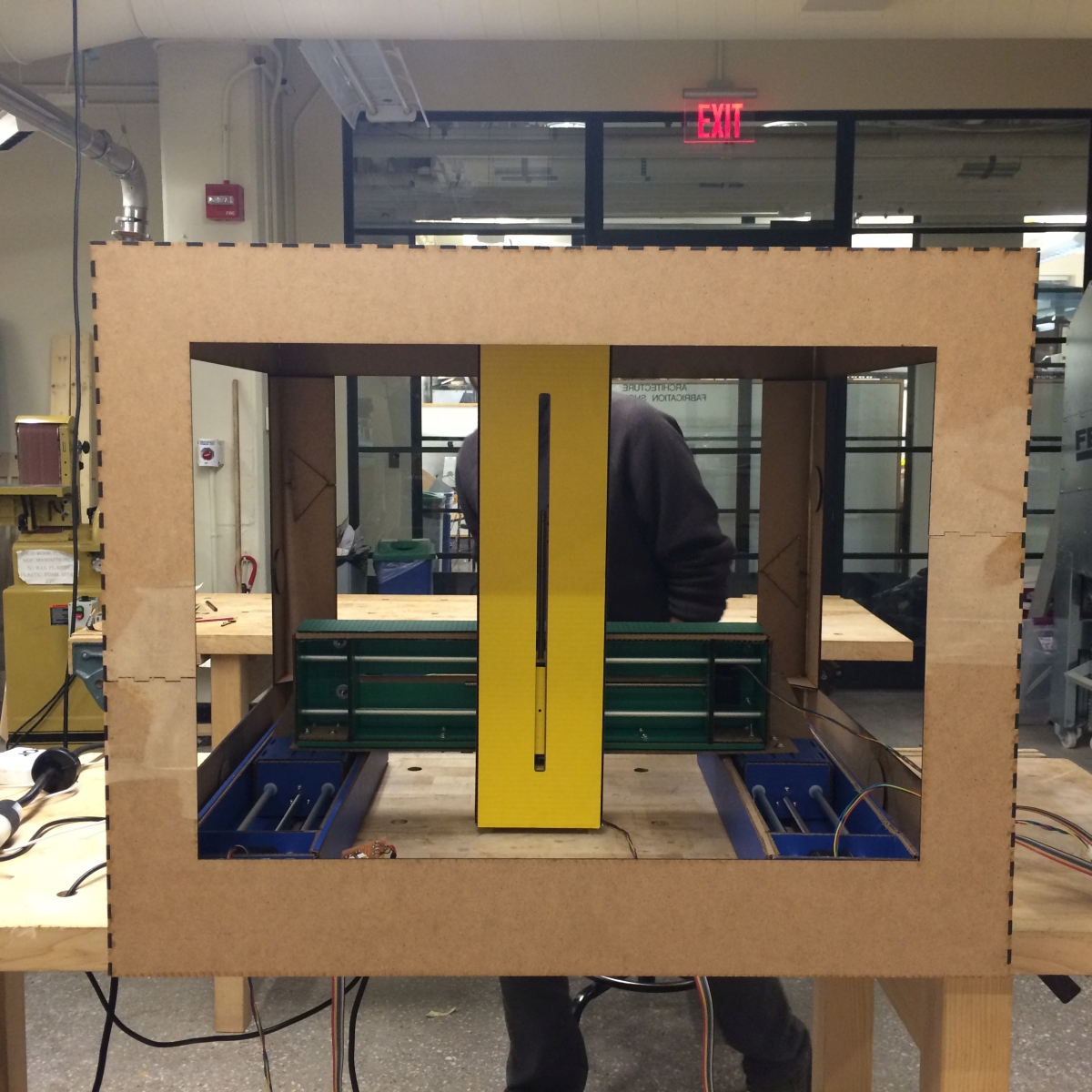
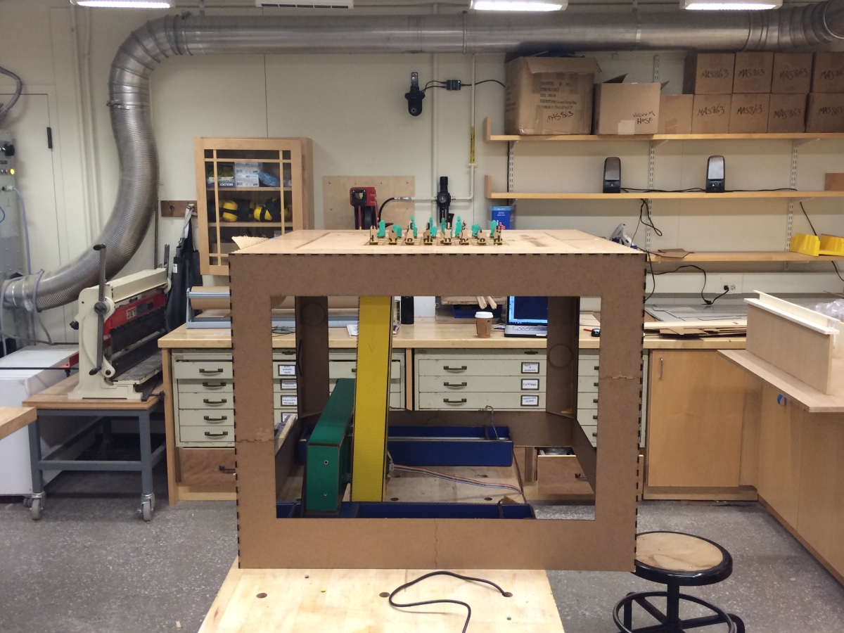
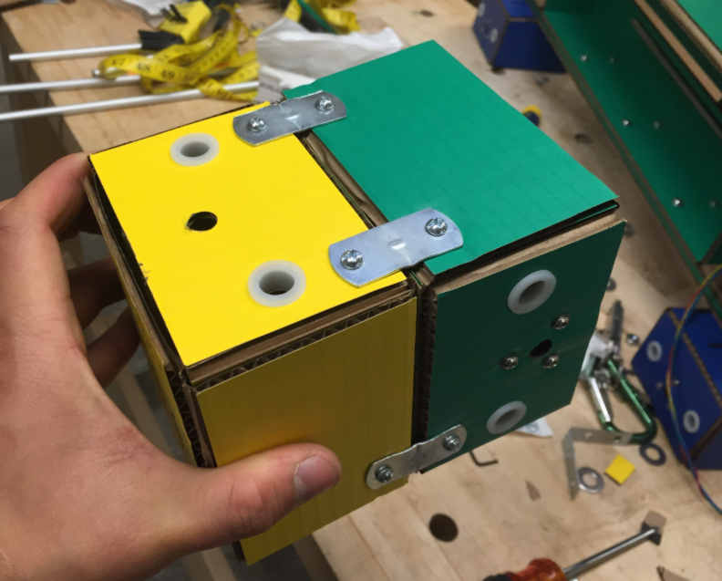
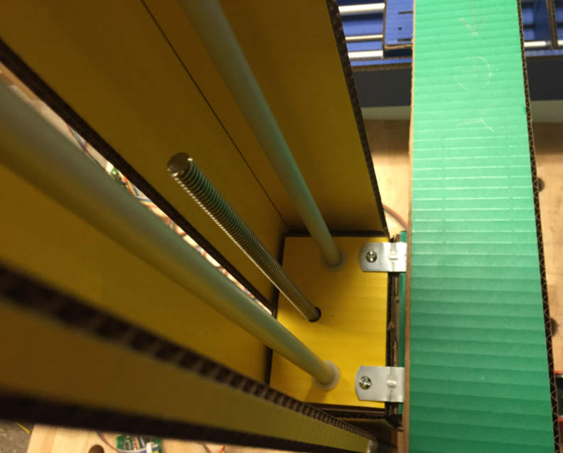
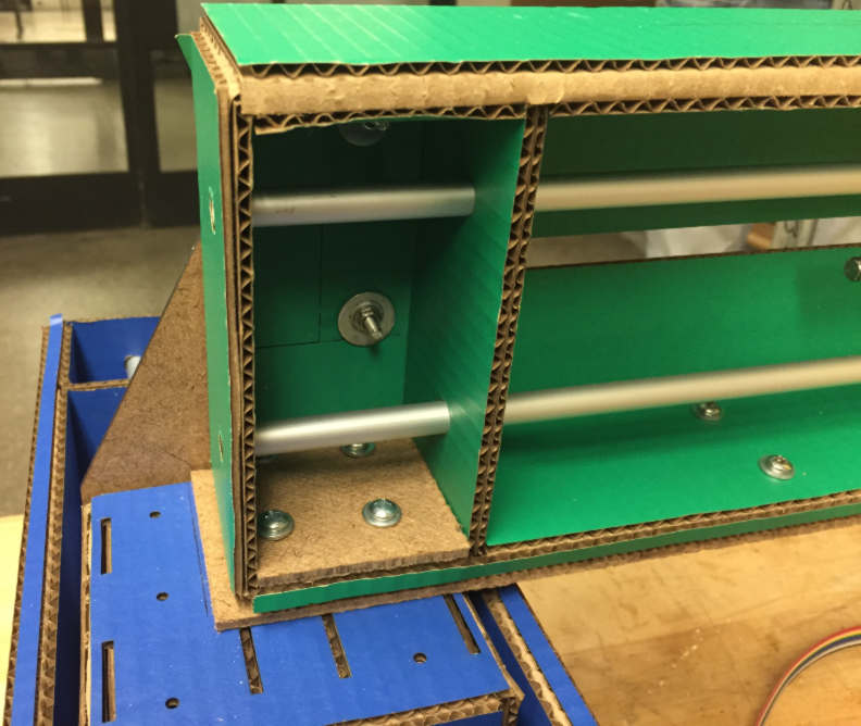
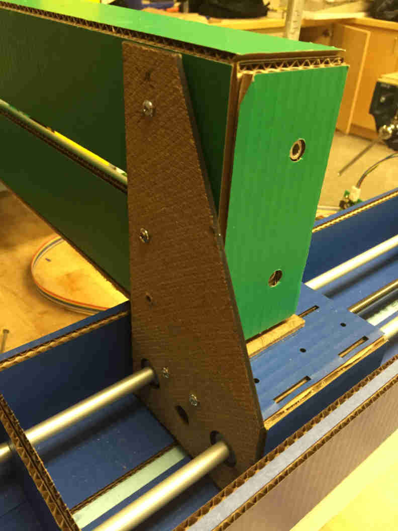
The actuators had to be connected to each other to allow for movement in the x, y, and z directions simultaneously. We found that the stiffness of the connections of the actuators was problematic due to the cardboard material. Extra holes were drilled and braces were added so that the material connecting the different axes was stronger. The most important joint was the x-y connection as the x-axis supports both the y and z drives. Below are some pictures of the braced and connected axes:
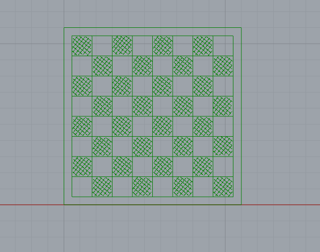
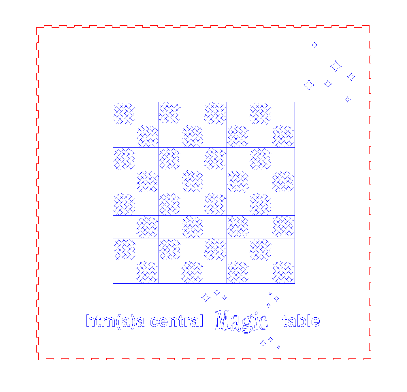
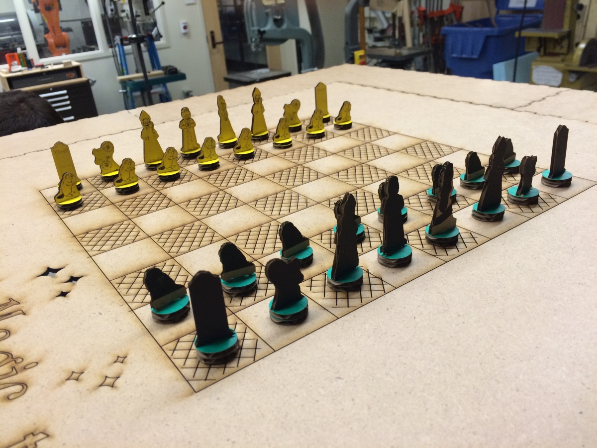
Simultaneoulsy, some people started to work on the chessboard design. We started by measuring the maximum distance the machine could move in the x and y directions. The maximum distance is approximately 11.5 inches along both axes. This gave us the constraints for the board. To be conservative, we decided to go with a board that would span 11 inches by 11 inches. A chess board is 8 spaces by 8 spaces, so we decided to make each space 1.25 inches by 1.25 inches (making the spaces span 10 inches by 10 inches) and leave a half-inch perimeter around the spaces as storage for chess pieces that get "killed." We decided to use masonite as the material for the board because it was available and it is suitable for a magnet to be controlled across the width of the board. The board design was scored by the laser cutter into the masonite. The board design can be seen below:
This 1.25 inch spacing set the constrint for the magnets. Some people then worked on finding and setting up magnets so that the magnetic field was weak enough to allow one magnet to pass between two magnets that were only 1.25 inches apart. The video below shows the challenges with the strength of the magnetic field:
IMG 2685 from Rich Li on Vimeo.
By manipulating the orientation of the magnetic field and turning the magnet sideways, the desired control was achieved. Below is a video showing this new control.
IMG 2695 from Rich Li on Vimeo.
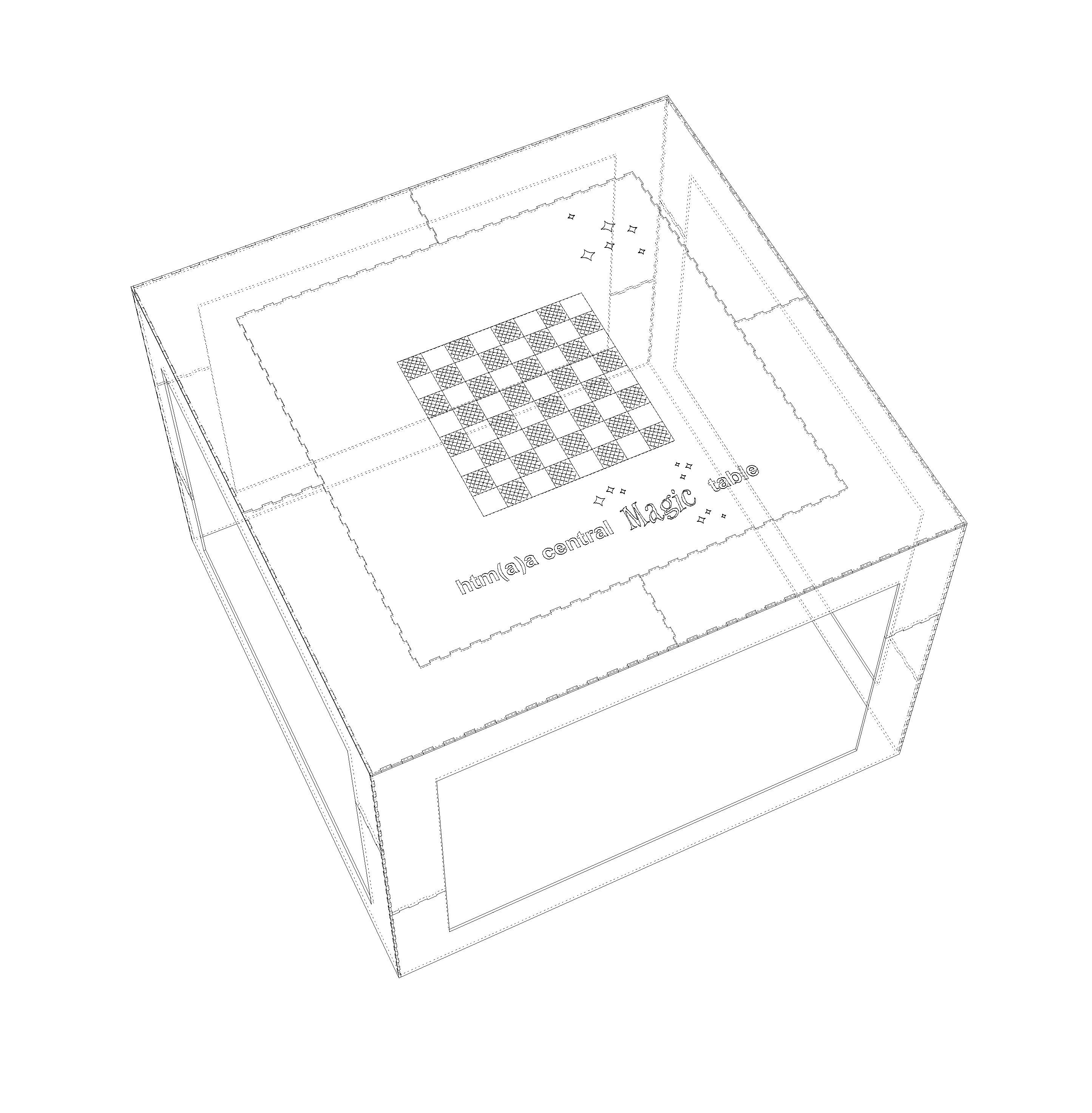
The next consideration was how to place the board above the machine. We decided that it would be cool to have the machine enclosed inside a box so that it would not be seen as the game of chess was being automatically played. However, due to material constraints, we ended up choosing to design only the edges of the box with a flat surface on the top for the board. Using the machine size as a constraint, we decided that the box would be 31 inches by 31 inches by 31 inches. The masonite pieces we had available were 32 inches by 16 inches. So, we decided to design teeth for the pieces of the table to press-fit together. The depth of the teeth were designed to be the width of the masonite. The table design from Rhino can be seen below:
The surface press-fits into the table perimeter
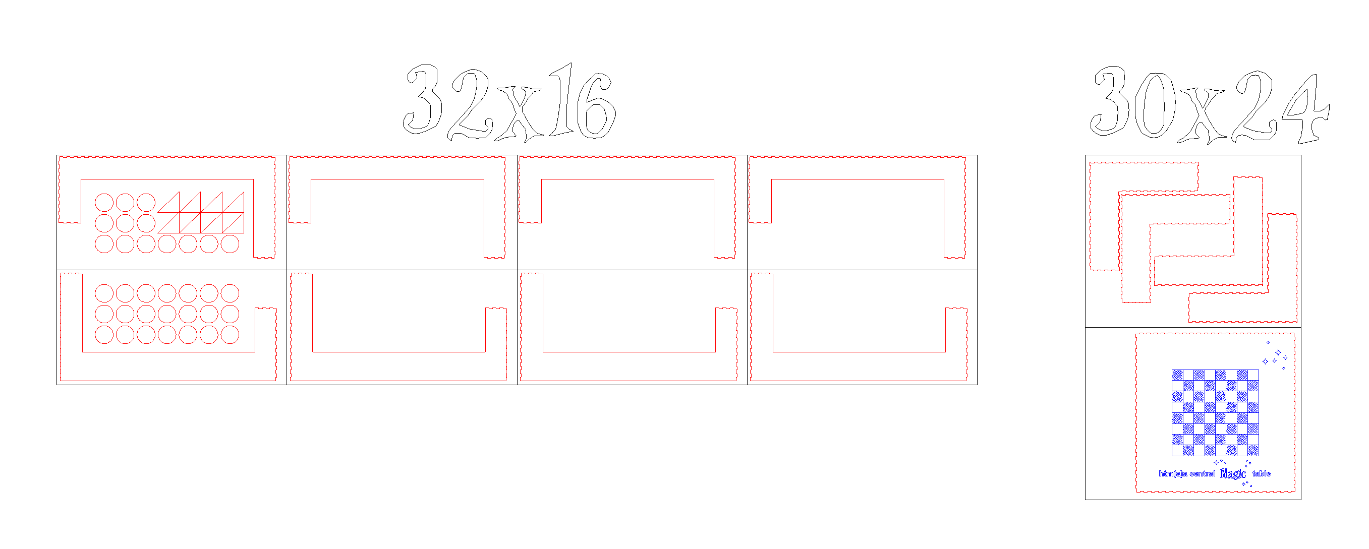
All of the pieces to the table
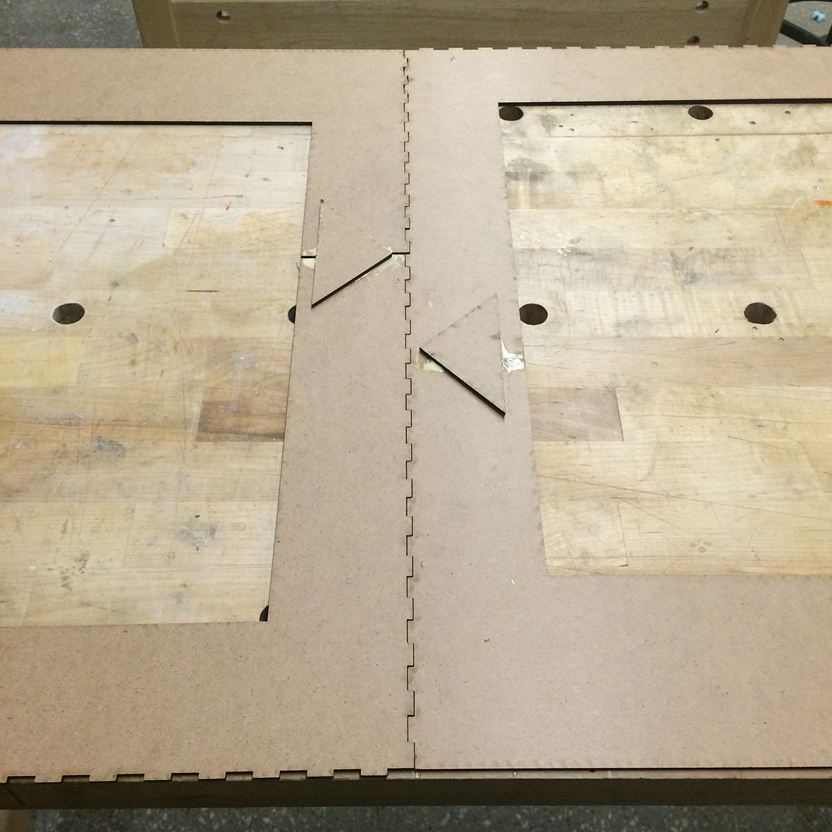
Once the designing was completed, we laser cut all of the pieces. Below are some pictures of the joints:
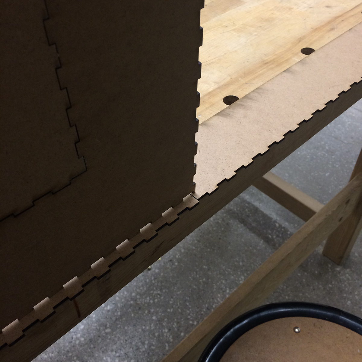
The corners
A general joint
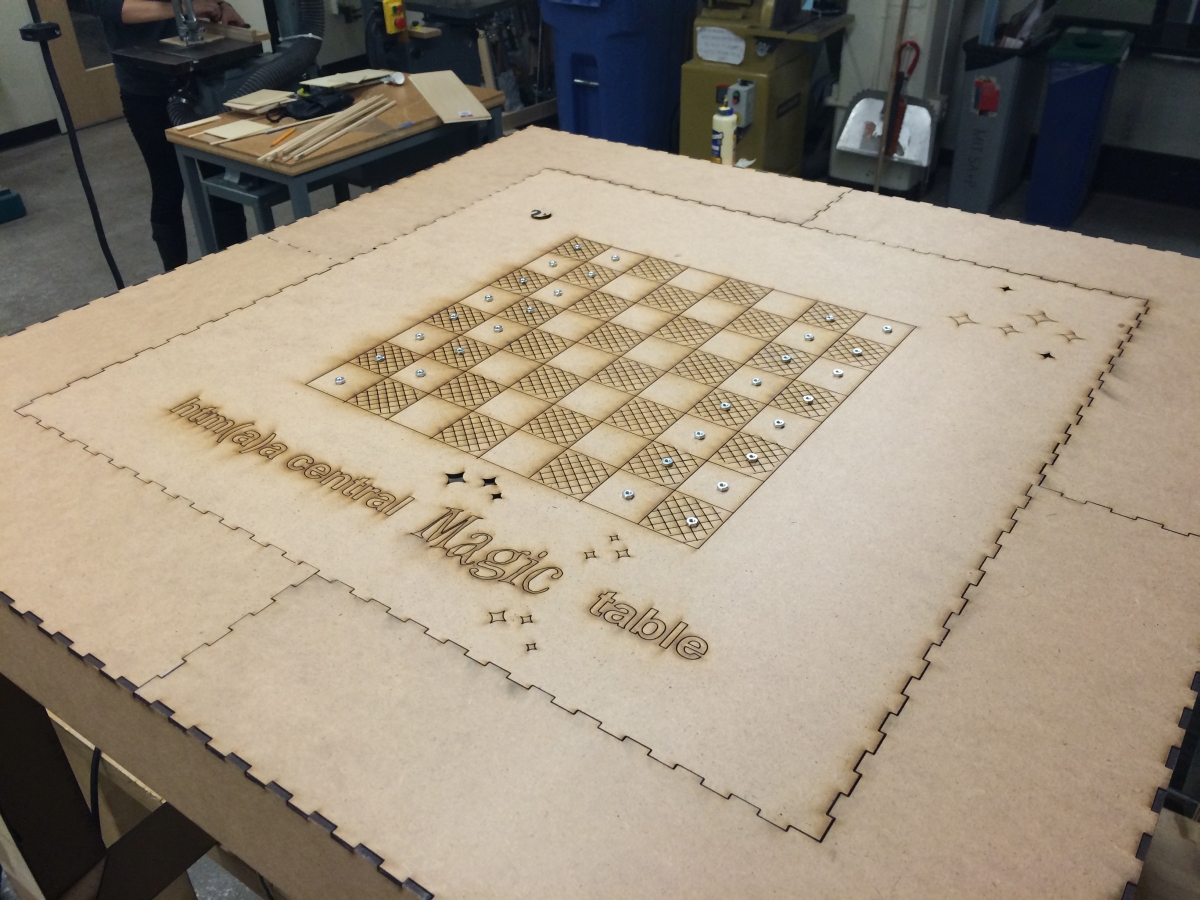
The top
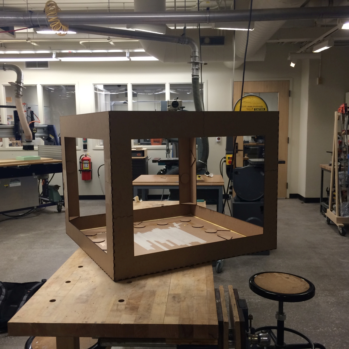
The whole table together
Some preliminary videos of
movement testsThe entire board:
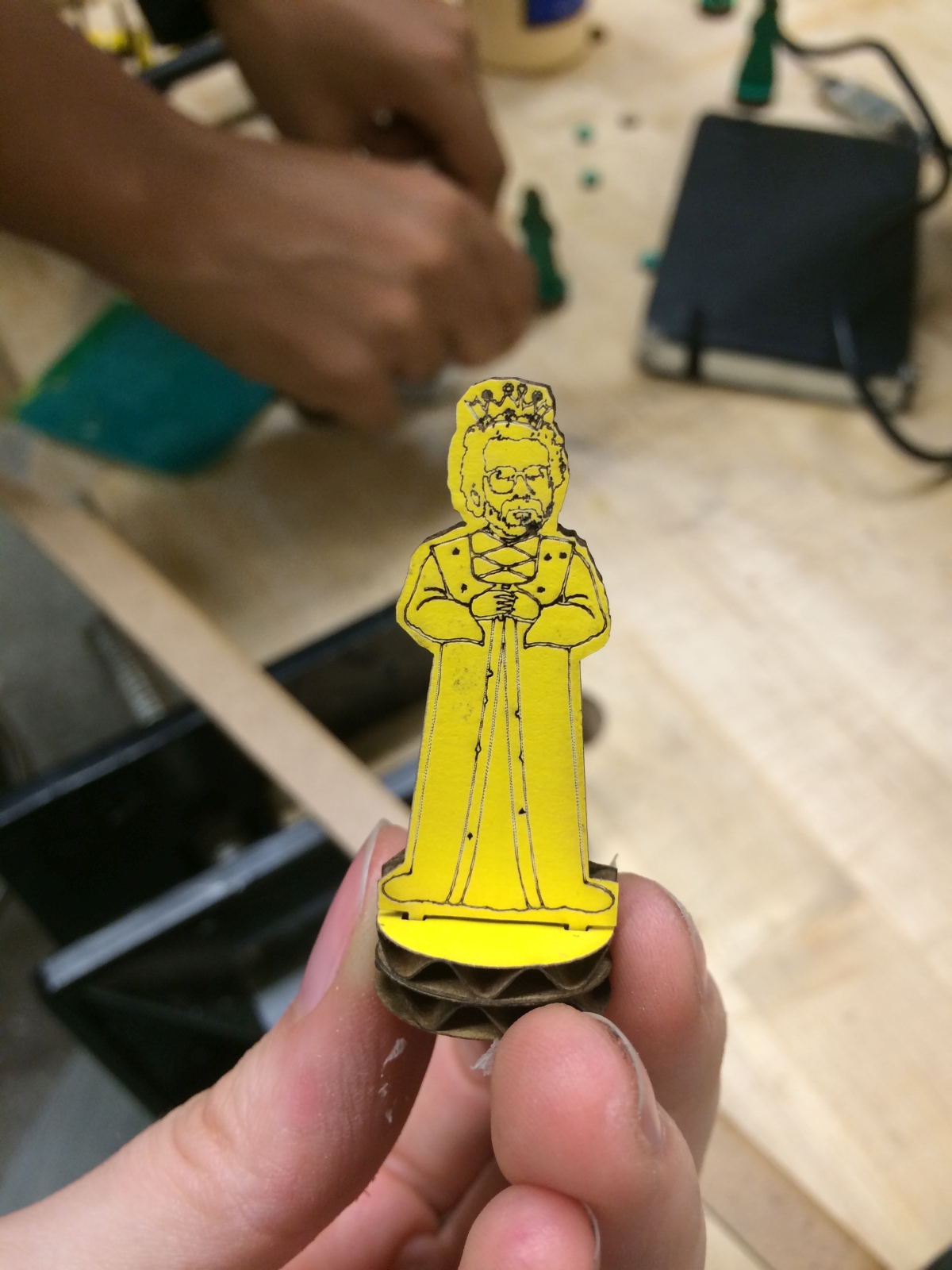
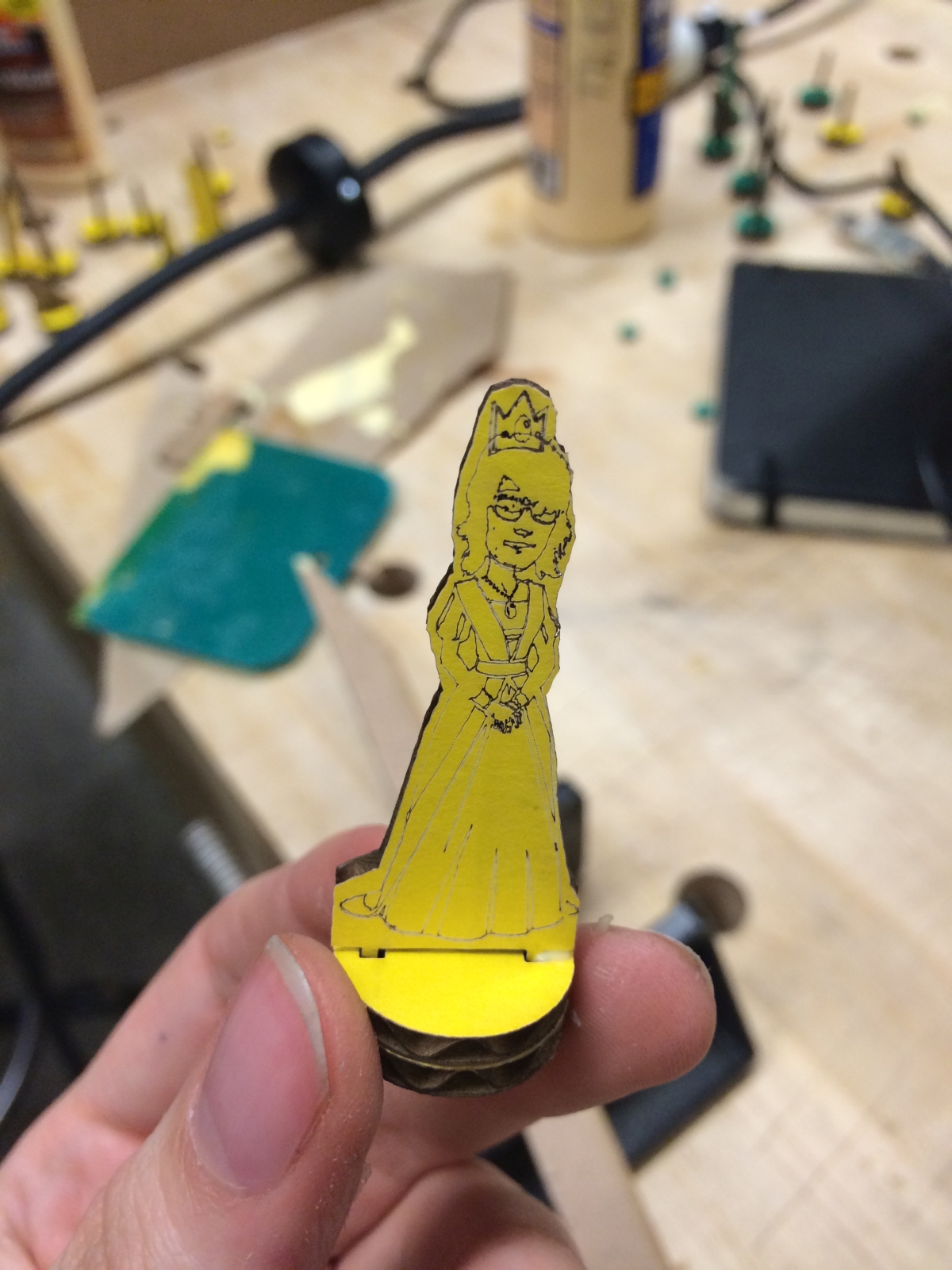
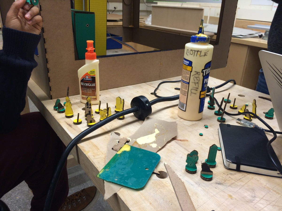
At the same time, some folks worked on designing the chess pieces. These were to be made from cardboard, laser cut, and then attached to magnets. Below are some pictures of chess piece design and assembly:
Meanwhile, others were working on writing the software to control the machine. (Add written documentation here).
Once all of the different components were prepared, we were able to put the machine together. Below are some pictures of the final assembly.