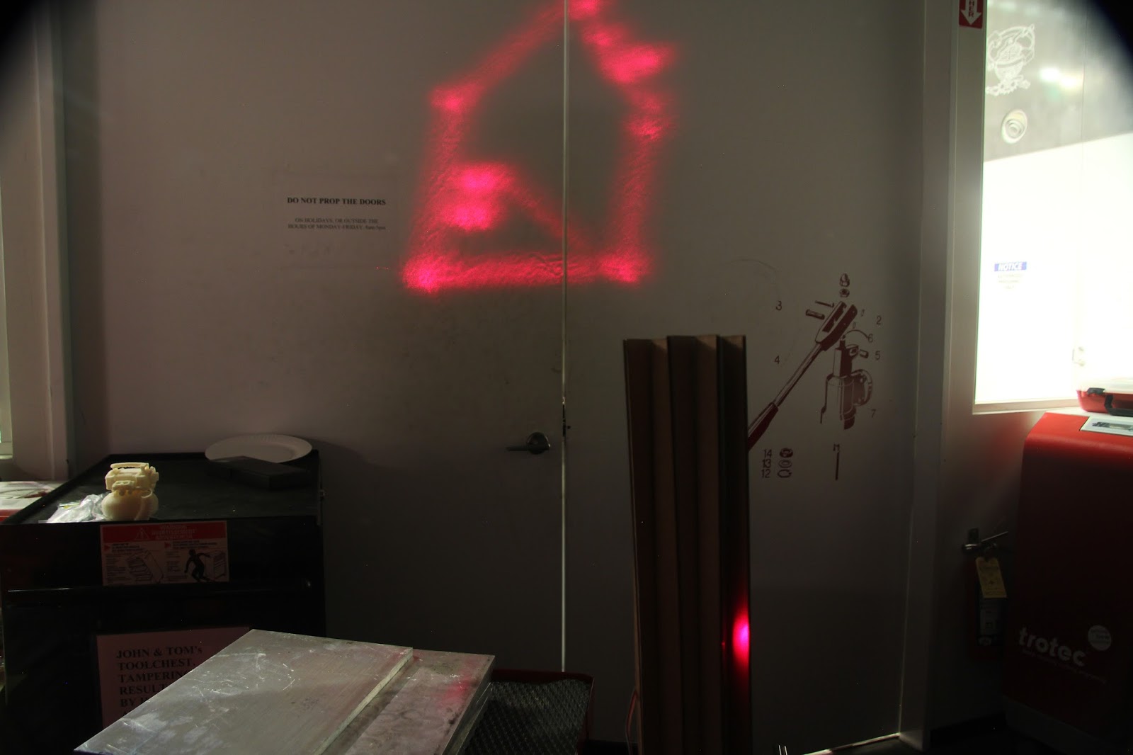
What we are building? In short we were building an automated light pencil, whereas to see the beauty of its art you need either a good memory or a time integrating device such as a camera.
So we could call it e.g. “a painting slowly with light-machine”
We met before the tutorial with Nadya and James for our intro session; a group consisting of primarily Media Lab people soon focused on a combination of technology and art; so our machine should be an artist but should also be able doing something hard for a human to perform; using light was the next step, and a laser was selected as light source in favor to an LED.
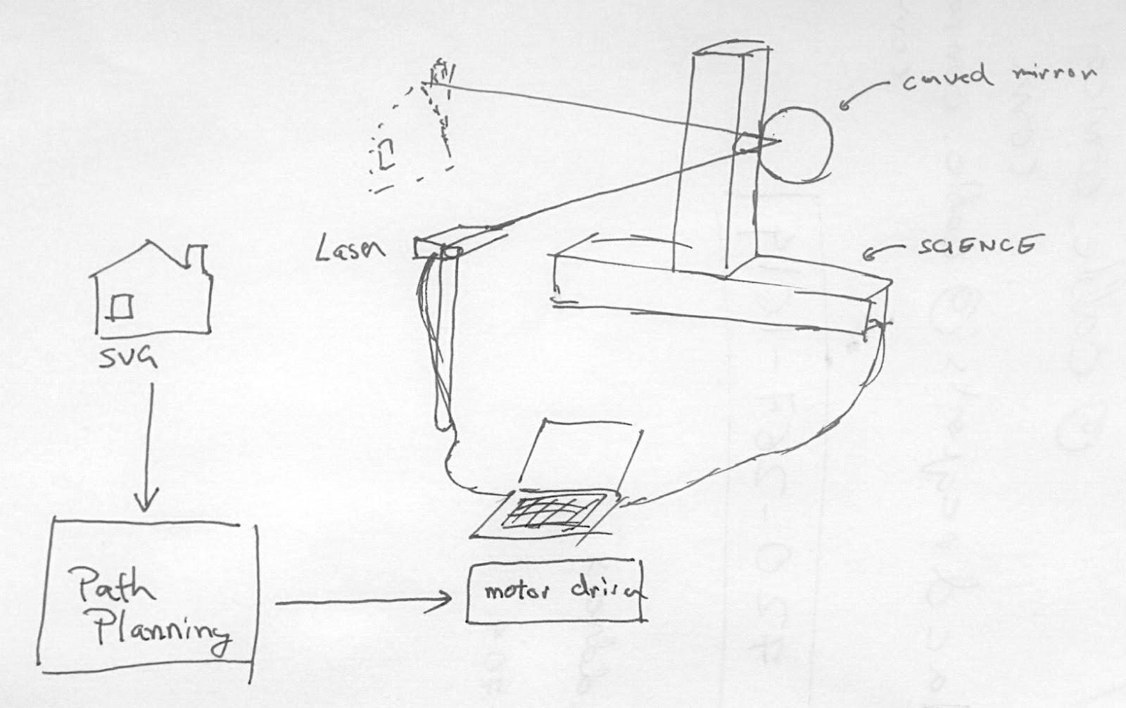
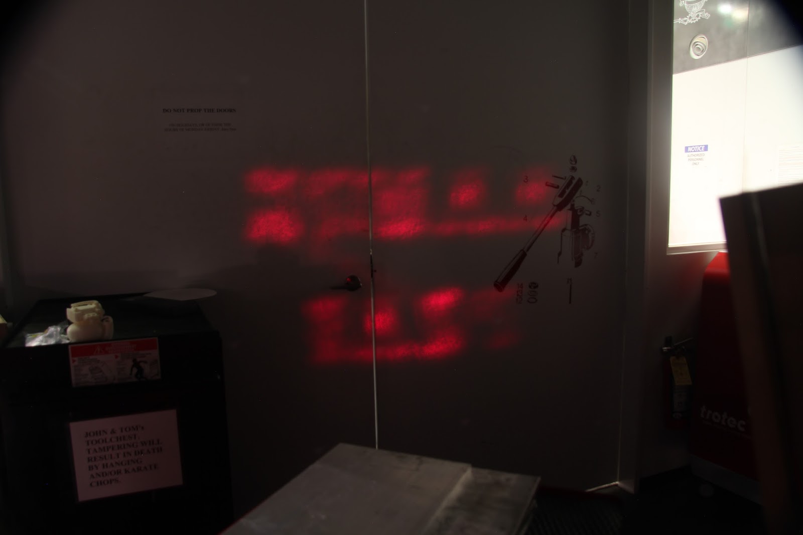
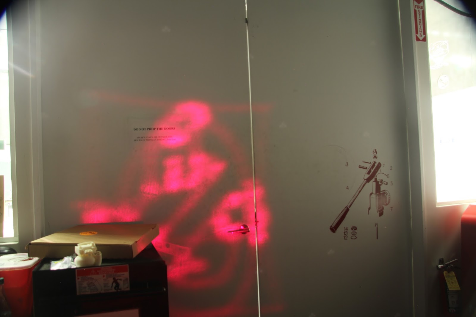
Since the group task was to build a machine supported by the modular stages concept driven by the pyGestalt virtual machine network, some frame parameters were given - two stages driven by stepper motors, a large one 1 square feet operating area but comparatively slowly. So we decided for the following concept: A control mechanism pilots a laser beam on a canvas, and a digital camera with long exposure time records the light path.
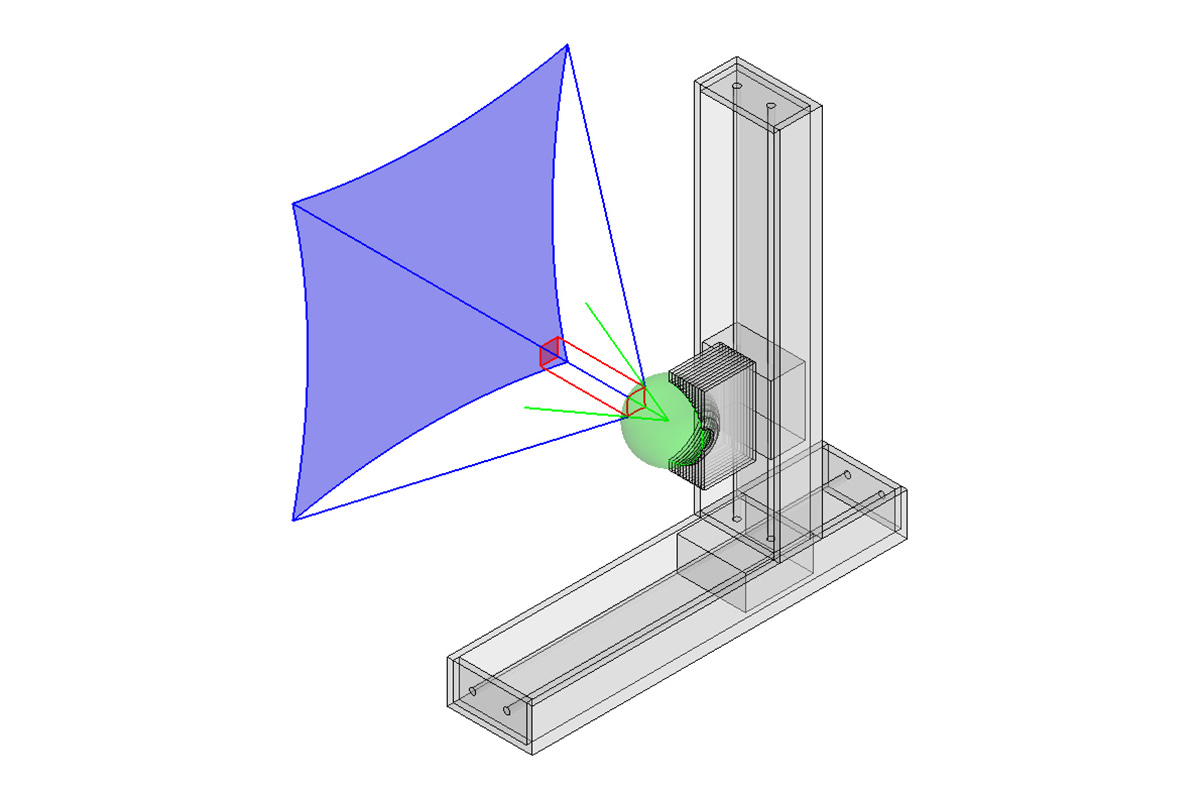
Since we wanted to use the XY-gantries, we decided to realize the angle dependency by a spherical mirror. It appeared also more promising to move the mirror instead of the laser, so the laser gets fixed, and the spherical mirror is moved perpendicular to the incident laser beam. In the following the individual sub-groups summarize their tasks.
Some of us had previously seem images of laser drawings like the one below:
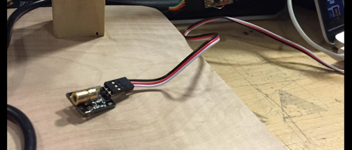
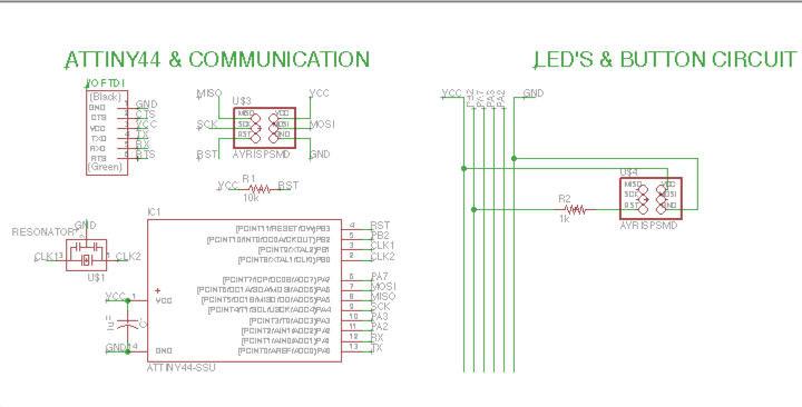
Our group’s task was to get our hands on a laser and then program it to turn on and off via serial commands, so that it could be controlled by our team’s path planning code. First, we experimented with a number of different laser options: Thras had a laser pointer, Dan had a chip with a laser embedded on it, and Thras also showed the group his lab’s laser down in the CBA. We settled on Dan’s chip for ease of use.
We realized that we could power the laser using Neil’s Hello LED board, and so we went ahead and replicated this board with a connection to our laser, which has 3 pins: power, ground, and on/off.
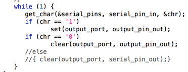
Next, we modified Neil’s code to be able to send ‘1’s and ‘0’s serially. Here’s the main loop, where we’re just referencing RX as serial_pin_in and output_port as the laser’s port.
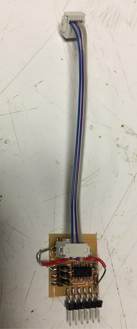
We used the Arduino serial in/out UI to send ‘1’s and ‘0’s. At first, it worked only once and not in subsequent attempts. We realized that this is because the baud rate setting of our serial commands did not match the chips. (We had it set at 9600 but the chip expected 15200.) Once we changed this, it worked like a charm. Here are pictures of our board and our laser
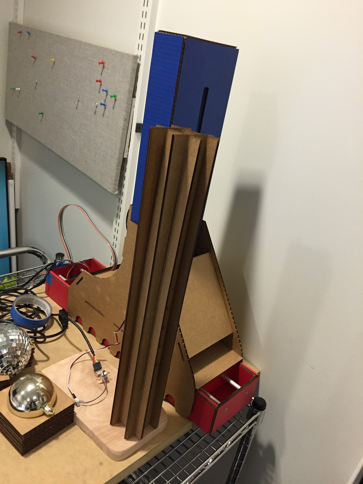
Our group-task was preparing the mechanical setup for the laser, from the general laser arrangement, to optics and fixation. Therefore our main interfaces were to the laser electronics group as well as the gantry-group.
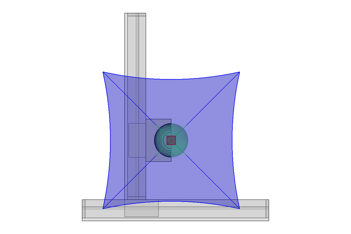
We had now to deal with the situation that we had a comparable slow XY-gantry system, and want to combine a laser, which gets applied for such a variety of tasks especially when it comes to ultra-precision and, with special lasers, to ultrafast time resolved measurements. In photonic-applications you typically avoid moving a laser – it’s often heavy, sensitive to movement and electrically connected. Instead you move small and lightweight mirrors which define the light path. An easy way to do it would be by having the plane of the mirror rotating, and switching the laser on only at the angle where the correct light path is given; using stepper-motors would be an option to without extra synchronization. However, we want to work with two gantries, so one way to reduce the lack of speed is to make travelling paths short. But how to control the reflected laser angle dependently by its XY-position so that it can screen a large field of view; we choose the approach using a curved surface, an easy one being a spherical mirror. Given the parallel incident light from the laser (incident vector), you just have to know the point where the reflection occurs, and the vector of the reflection is therefore known. So we have a Cartesian to Polar transformation. The inverse is also true. The transformation matrix will always be the same for each input pixel or XY-representation, so it has only be calculated once and stored in a lookup table. It can be performed on the imaging side or the driver side, but it would make sense to do it on the image side to save process speed (though not critical with this application).
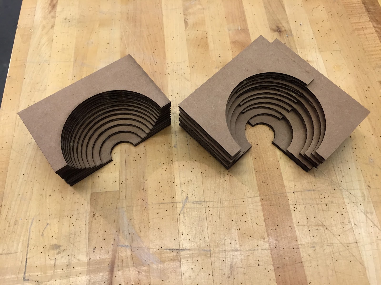
For a cheap spherical mirror we decided to use a mirror coated ball used for garden decoration, a mirroring silver Christmas ornament, or even a disco ball with small discrete mirrors. One simple quick fixation method is to make a number of single laser cuts, varying their out-cut radius by the sphere shape (therefore following a cosine function), such slicing can be performed e.g. in rhino.
As a laser-source we used the laser-pointer of a group member; at this point, some general words to laser safety are required. Though laser pointers (as used in our group project) are a kind of commodity product, such lasers can be harmful, especially for the unprotected eye. This is often underestimated, which might have to do with at least three facts; first, given the small divergence of a laser beams, the risk potential does only decrease slowly with distance; second, given the long interference length, the strong intensity can be reached even at small power intensities; this gets even more problematic with pulsed lasers; here, the mean energy is set free in short time intervals, leading to high intensity amplitudes. Third, the risk and danger has to do with many variables, such as wavelength, pulse length, exposure time, etc. To deal with that, lasers are classified, and each laser should disclose its laser class and therefore the risk involved with its use. The problem here is that such labelling is sometimes missing or even wrong. Everybody working with lasers should be aware of the above mentioned.
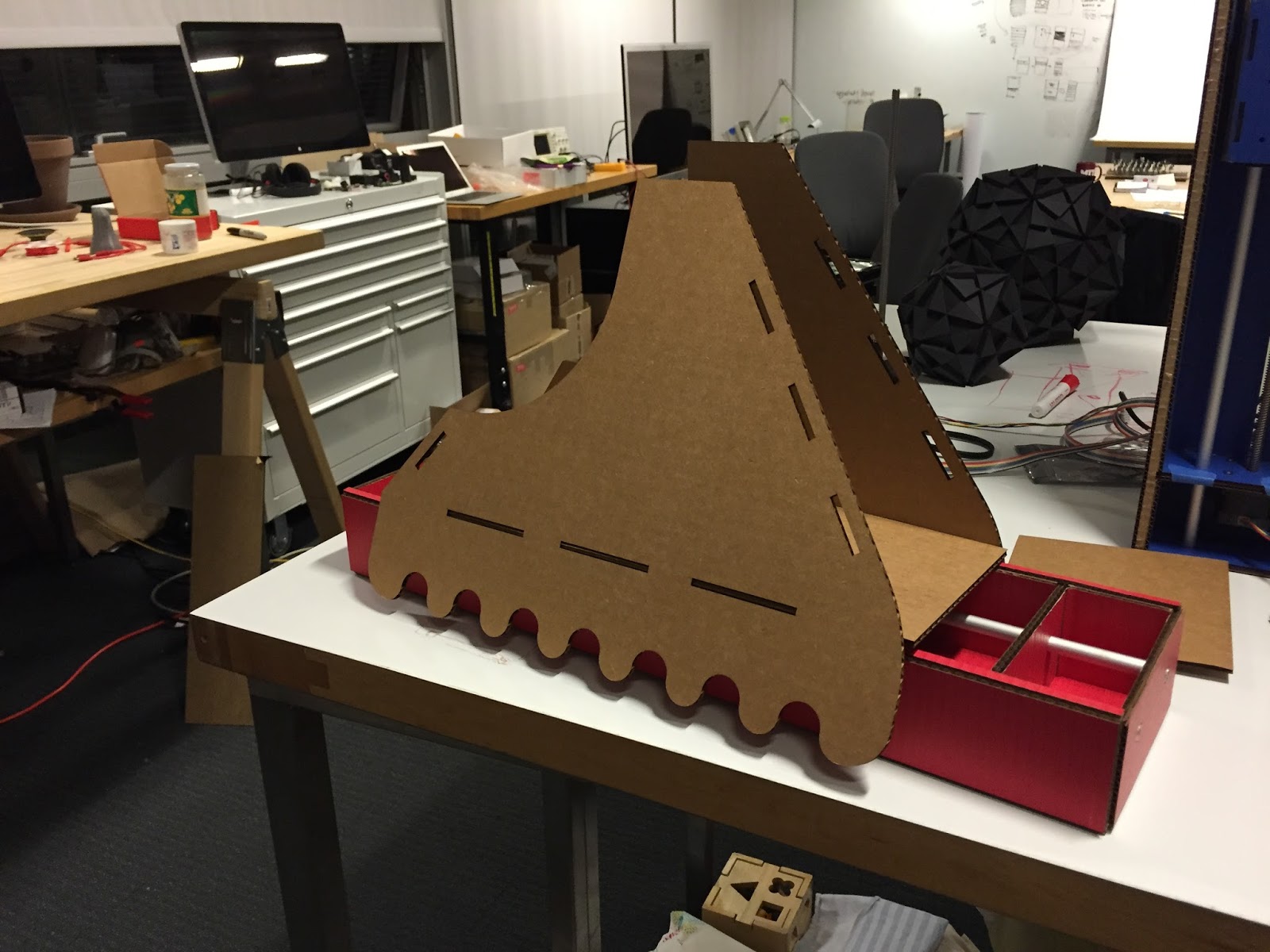
Two key elements of machine design, as mentioned by Matt Carney, are constraints and stiffness. The task of creating a mechanical rig for long exposure photography means that the machine needs to be rigid and have little to no kick back. Given that the laser team chose to move a mirrored ball on the gantry, the cardboard setup would need to remain stable with a significant cantilever.
Task 1: Create a 2 degree of freedom platform. To create this platform, we decide to mount one of the gantries to the trolley of the first gantry. This seems to be a simple task at first, nothing a little hot glue or other adhesion method can’t handle, but then there are the forces on that joint.
Mounting the tall and skinny gantry to the bottom long and skinny gantry creates quite a lever, which needs some way of not tilting (creating torque) at the joint, which needs to remain at 90 degrees for both accuracy as well as strength.
Task 2: Remove stress at join to maintain orthogonal gantries. Our solution to this problem was to add a set of flying buttresses to the Y-axis gantry. A simple triangular strut from each side of the vertical gantry would be enough to reduce the torque on the joint as well as provide a new constraint by widening the base that will be translating. The cardboard construction of this support uses multiple cross braces to ensure rigidity. One aspect that might look funny, or cool, depending on your viewpoint, is the bottom of the supports. Since the supports need to make constant contact with the ground and translate with the top gantry, it is important that it not create too much friction while moving.
Task 3: Reduce friction on support. One possible way to reduce friction is to change the material. Cardboard is already quite low on friction, but there are definitely materials with smaller coefficients. Another way to reduce friction is mechanically with a component such as a wheel or bearing. Lastly, we decided to use the materials at hand and use the form to reduce friction. Turning the bottom into a series of half circles. that will only touch at a single point. Triangles or a sine wave could have also worked. Circles were chosen for simplicity, strength, and aesthetics.
Once assembled the support system provided smooth movement without any load on the top trolly. A promising first step for the Mechanical Engineering.
This code integrates path planning with gestalt and laser control. It takes in a csv with both motor positions and laser on/off controls and talks over usb to the respective control circuits.
best explained in code:
def run(stages, moves):
for move in moves: # moves is the csv file
laser_val = move[-1]
xy_move = scale_xy_move(move[:2])
set_laser(laser_val)
move_motors(stages, xy_move) # blocking
Example CSV:
ubuntu:code$ cat moves.csv
0.0, 0.5, 1.0
1.0, 1.0, 0.0
0.5, 0.5, 1.0
1.0, 0.0, 0.0
output of the code:
laser on
moving to (0.0, 0.5)
laser off
moving to (1.0, 1.0)
laser on
moving to (0.5, 0.5)
laser off
moving to (1.0, 0.0)
SVG files are converted to Gestalt motor commands in path_plan.py (863.14/projects/east/code/path_plan.py in the repository). SVG files can of consist paths, shapes, text, and other features, but our code will only handle paths and ignore all other features. A path can be a line, an arc, or a curve. path_plan.py does the following:
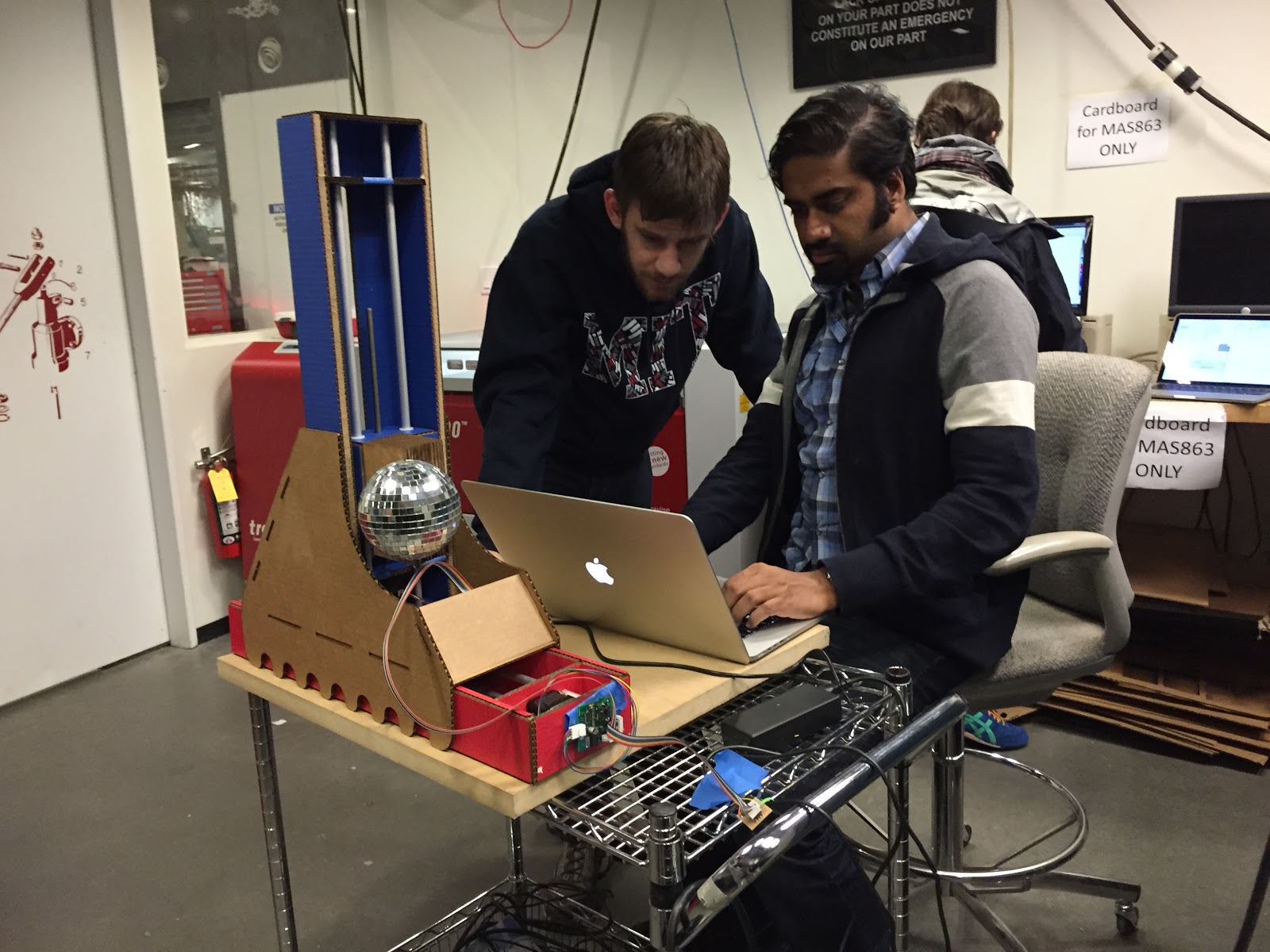
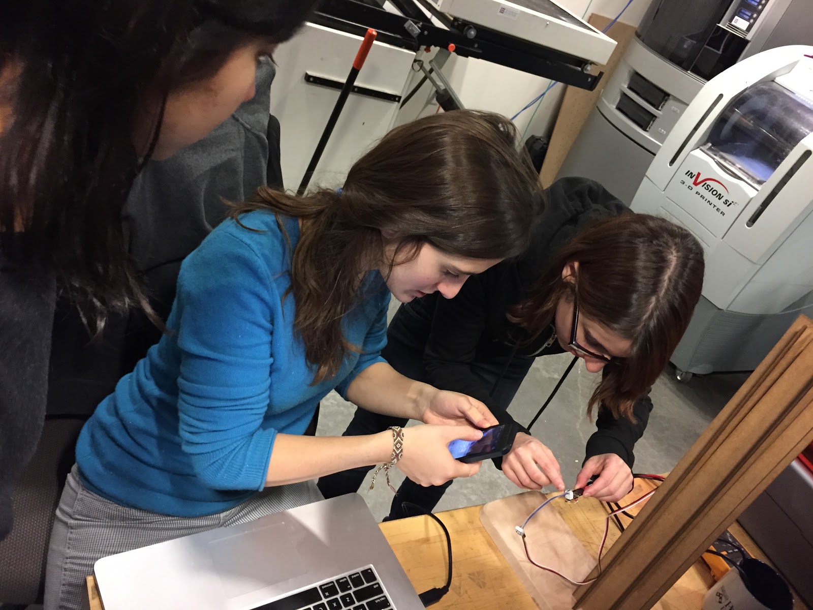
<folks, can you enter pictures you took of us doing the final assembly in the cba shop>
Getting Software Serial to work so we can fire the laser via serial
Vimeo of Ghostbusters