This week I wante to start to work on the final project. I am thus interested into 2 types of sensors:
- a pressure sensor
- a light sensor
Light Sensor
10. Input Device
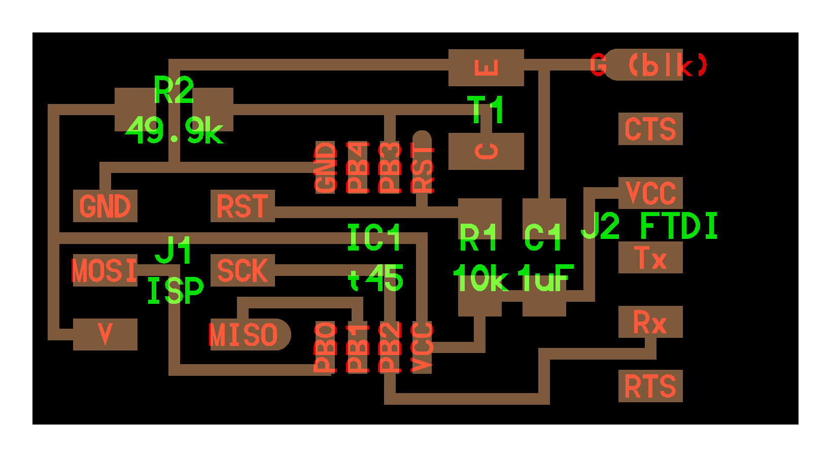
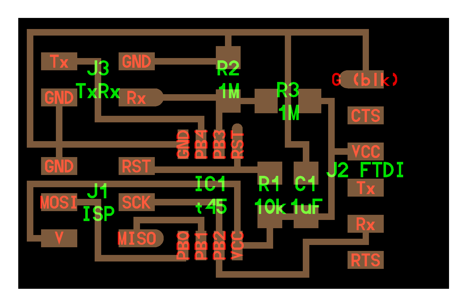
The devices to build a classic light sensor board are:
- A Microcontroller ATtiny45 (8 pins)
- A Photo Transistor NPN CLR PLCC-2 35V
- A 10kOhm and a 49.4 kOhm resistor
- A 1uF capacitor
- A FTDI port (Receive and Transmit)
- A 2x3 ISP header
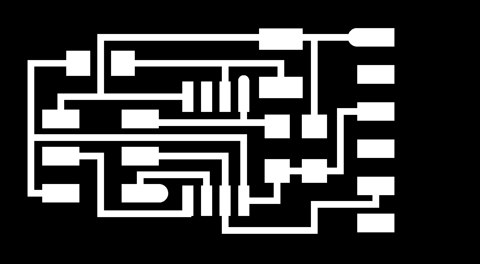
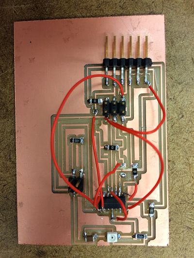
In a first time, I trained on the already built board that can be downloaded here: traces,interior. The process is similar to the previous boards milled and stuffed: milling with the Modela MDX-20 with the fab module interface: the traces with the 1/64" and the interior with the 1/32", and then stuffing the board.
I could then download the c-file and the make-file to program the board. The c-file is composed of different parts:
- The part defining the different routines
- The part defining the routine to send characters on port pins. It defines every pin of the ATtiny 45 and set it to a value. This part of the code might need to be changed when we switch to ATtiny44
- The main loop, where we do to actions: initializing the oupit pins and the Analog to Digital routine, and the main loop where we actually collect the digital output
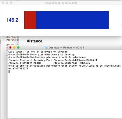
For now, this part has not been too documented because it is a similar workflow than previously. But now, what is new is that we will need to run an interface in python to be able to visualize the actual light sensor. We use the Python file to create the interface. To call the python file, we go to the directory where it has been download and we ran the instructions:
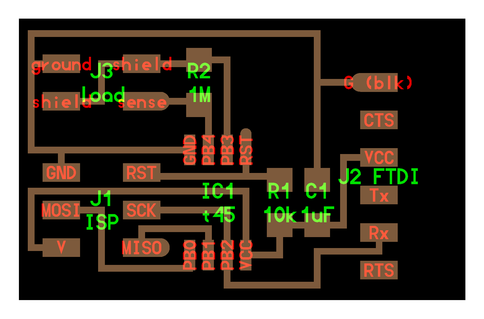
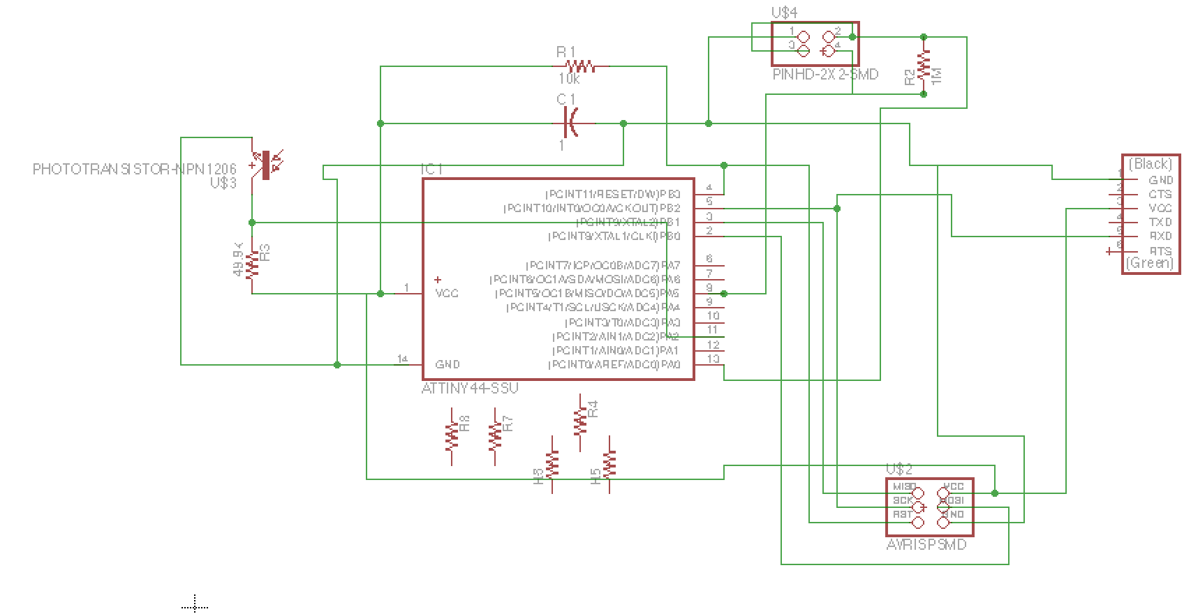
So the goal was to have a board being able to read to types of sensors: the ligth sensor and the pressure sensor. The pressure sensor, using the load board (setp response) uses already all of the pins of the ATtiny45. So we will need to have another microprocessor to have ore ouptuts. However, we will see that, for the pressure sensor, by using the Hyper elastic sensor of silicon elastomer, changing resistance with loading, we can actually only use 1 pin of the ATtiny45, and thus do the two sensor on the same board. But for the final project, we will need extra pins to have output devices. We thus decided to use the ATtiny44 with 16 pins. The composents we need for this board are:
- A Microcontroller ATtiny44 (16 pins)
- A Photo Transistor NPN CLR PLCC-2 35V
- A 10kOhm and a 49.4 kOhm resistor
- A 1uF capacitor
- A FTDI port (Receive and Transmit)
- A 2x3 ISP header
- A 2x2 header output for the pressure sensor
- A 1MOhm resistor
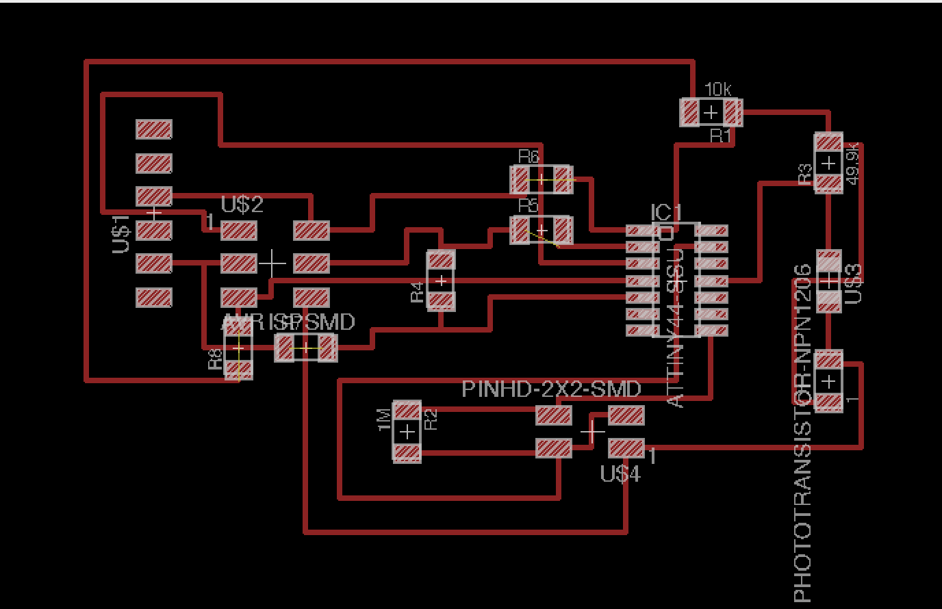
After having printed it (I will show a picture of the print + of the hack later), I stuffed it and then try to program it.
My firdst attempt to program it was to use the light sensor code from ATtiny45 and change it in ATtiny44 (for the make and the c files). I was not entirely quite sure what to change, so my major changes was to actually modify the pins from:
#define serial_pin_out (1 << PB2)
To
#define serial_pin_out (1 << PA2)
And by changing the line in the make file from
avrdude -p t45 -P usb -c avrisp2 -U flash:w:$(PROJECT).c.hex
To
avrdude -p t44 -P usb -c avrisp2 -U flash:w:$(PROJECT).c.hex
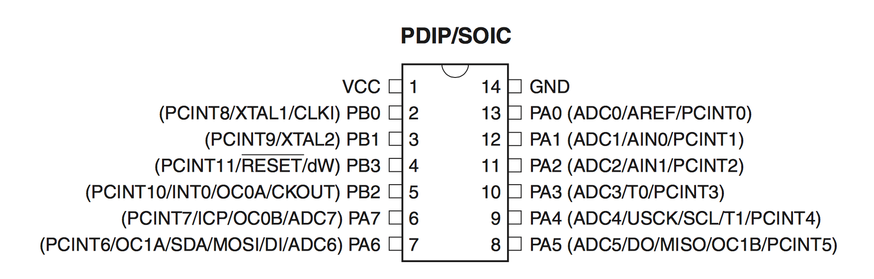
Then to run the code, I did the same process than before: make -f hello.light.44.make program-avrisp2. I had an error telling me that "PA2" was not declared. I think it is related to the fact that I am using PORT B in the code: #define serial_port PORTB and I could not change it without receiving an error. I thus read in more depth the ATtiny44 and ATtiny45 sheet, and I realised that I could not necessary interchange all of the pins like that.
Meanwhile, I also tried to bootload the board with the Arduino IDE. I ented those parameters:
- Board: ATtiny
- Processor: Attiny44
- Clock: 8MHz (internal)
- Port: usbserial-FTHBSO75
- Programmer AVRISP mkII
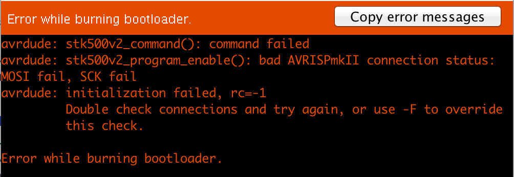
I double checked multiple time the connections and first, I noticed one issue with the ground:
- Finally, I also wanted to put the photostranistor output to a PB pin, so I hacked the board even more
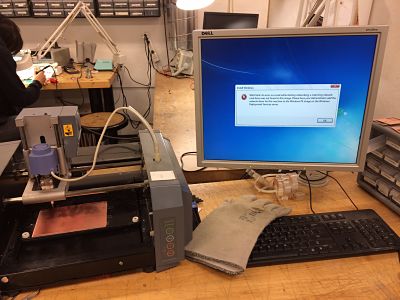
At this point, you could ask me, why did not I updated the Eagle design and remilled a new board. I actually did. The issue is that the computer driving the Modela encountered a fatal hard drive error and was unusable:
So I had to trouble shoot with the soldering iron instead. But then I tried to bootload the board, and :

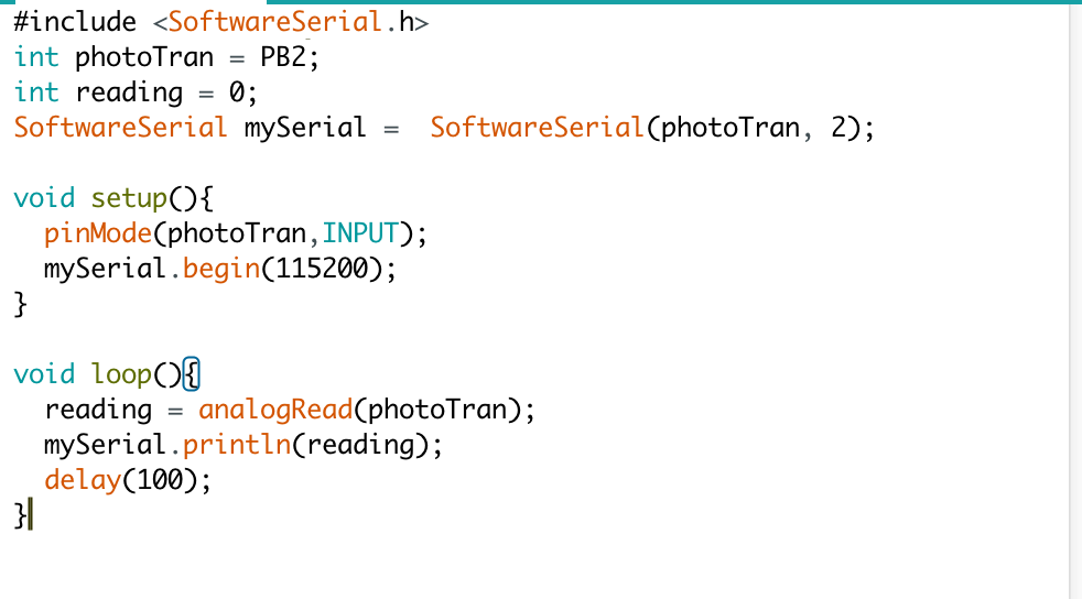
It means "HOURRRAAAA". I thus wanted to play a little bit withe Arduino IDE, and I tried to find example trying to read phototransistors. A good example of a code can be found here. They use the function "Serial", that return an error because it was actually not declared. It is because the new arduino interface uses the function SoftwareSerial instead. I also needed to make some steps showed on the previous example to make it work ("SoftwareSerial mySerial = SoftwareSerial(rxPin, txPin); and then calling "mySerial.begin(..)). At the end, I had the following code in Arduino IDE:
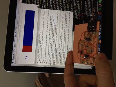
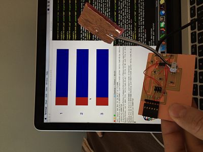
And... it actually... did not work. When I ran it, and opened the serial port, I could not see anything. I was not sure if it was a Arduino IDE issue or a board one. So I switched back to c-code and make file + terminal, and tried to upload the code. And it worked. Then I tried the python interface code, and it worked too (by that I mean that it opened the window, but then froze:
I believe that it is still an issue with the ATtiny44, probably hardware connection but it is weird that the ARduino IDE could bootload the board but not read the pin. Maybe it is two different issues. For the c code I think it might be an issue in the part of the code of ATtiny45 where all of the pins are sets, and I am not changing this part. It is now time to explain more the pressure sensor.
Pressure Sensor
10. Input Device
Two options (2.5 actually) can be done to mesure pressure: using a changing resistive device (the length of a resistance is modified by the load applied on it) or using a capacitive device (the capacitance of a capacitor is changed by the load applied to it). I tried to explore those two options. Let's start with the capacitance device.
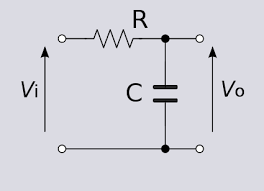
By bringing to conductive plate next to each other, we can actually create a capacitor. If we modify the distance between the plates, it changes the capacitance and we can actually read it in a pin. We can put a high resistance before and then read, as shown on the following picture Vo
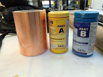
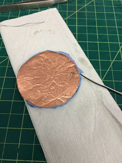
The previous board chose a 1MOhm resistor, for example. We can actually have an idea of the change of capacitance through deformation of the two plates by calculating the capacitance through the following website. The first itareration, I wanted to use OOMOO and thus I calculated the capacitance for two plates of diameter D=6.35cm (thus area of A= 0.0032m2) and seperated by a layer of OOMOO of thickness d=0.45cm. The dielectric constant of OOMOO is 3.33 and can be found here. I thus have a capacitance of 2.0966e-11. I then started to draw some circles in Rhino of diameter D=6.35cm and 3D cut them in transparent plastic. Then prepared the OOMOO (I did it kind of quickly) and cast the OOMOO. In the same time, I cut two copper layers of the same diameter. Here are pictures of the process:
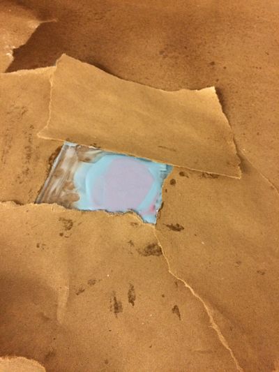
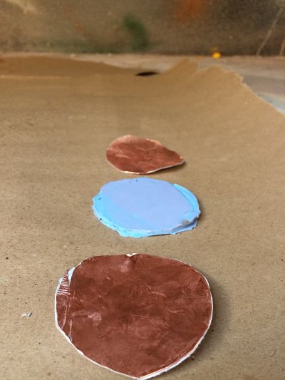
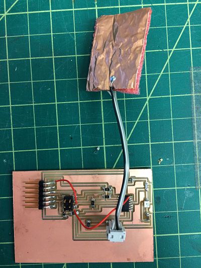
You can see that the OOMOO was not perfectly mixed. I then solder to wire on each copper plate and assemble it. I first tried to use the load board showed here:

I can see three different pins: Sense, Shield and Ground. I was not sure to what connect the shield and assumed that Sense whould be one plate and Ground the other. Neil explanation's are: "The shield connection is only if you need a driven shield for a long cable run, but it's much better to the put the processor at the electrode. And the ground is just a convenience for testing and calibration, to apply known loads." It is this design that I implemented in the light+load board described previously. The other solution can be to use the transmit/receive board described as follows:
It will probably switch to this design for the final project because I can control both sides, rather than loading, which relies on room ground. I still tried to make the loading board work. First, I actually changed material because my loading sensor with OOMOO was to thick to be really deform with pressure, and instead I used foam and put the shield wire in the middle of the two sense and ground wires.
The issue is that here, I still had an issue with the traces. I hacked it even more because the Modela MDX-20 was not working anymore, and tried to run the code by changing ATtiny45 to ATtiny44 in the code:
For the final project, I thus want to make a new clean board with the Modela (when it works) with the appropriate pins, using the transmit and receive probably, transmit from the top and bottom and receive from the middle, to screen outside loading.
Finally, I also wanted to test the resistive way of sensing loading. In my lab, we developed this resistive sensor using hyper-elastic silicon elastomer where a microfluidic cannel filled with gallinstan is connecting to pins inside. This sensor is used for inside spacesuit pressure sensing (slide credit: Allison Anderson).
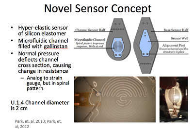
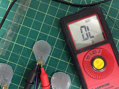
By coupling the changing resistor sensor to the a pin (and having another resistor between VCC and this pin), we can actually sense pressure by change of shape, and it will require only one pin to do so. The issue is about the change in resistance: it is very small (see the video), and thus will need to be amplified. The issue with that is that the sensor is very small to feel a modification of pressure across the bike seat and thus the reading can be very noisy, so the amplifier only might not work and we would need some type of filter(probably low pass filter) to analyse the signal. Given thse complications, I will probably stick with the transmit receive step response:
Some part of the code needs to be changed also. It is the ADMUX part. It tells the microcontroller which pins will read the analog to digital signal, using this code. This website explains it well.
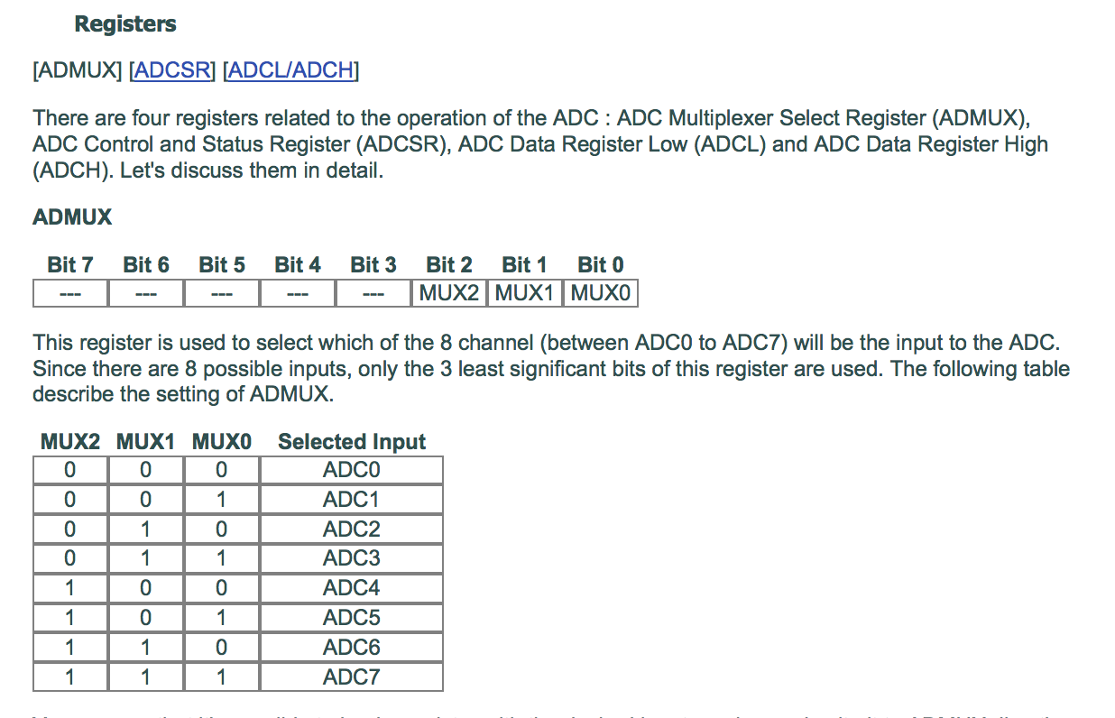
I thus changed the ADMUX to select a ADCSR pin (PA2 that was connected to the light sensor for example) using this code:
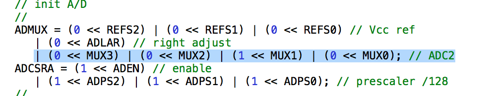
We can also have an error from the code because it does not know the variable "REFS2", so I just removed "(0 << REFS2)".
Last, but not least, I made the temperature and 3D accelerometer board from Neil, to train on them, and also for the interface week, to make sure I have boards that work. I encountered some issues with the Python code for the temperature sensor that requires numpy and I had issues to install it properly. I did the hot air gun technique to solder the 3D accelerometer. For my new light sensor and the accelerometer, I could program the board but not make the python code worked, because it seems it was frozen. For the temperature board, it was just an issue of numpy that I need to troubleshoot for the Interface Programming week.