Week 9: Output Devices
make it do something else
The Assignment
add an output device to a microcontroller
- The Problem:Improve on the poor performance from last week and get a motor to move!
- The Solution:Try another method to better understand how circuits and programming work. Try out an arduino starter kit to get me a little more certain of what's going on, and then try to get a stepper motor to work with a board I milled.
- Time Investment:10 hours playing with an Arduino board, 5 hours getting from copper board to moving motor
Learn to crawl
before learning to walk
After Niel's comments last week on my Embedded Program page from last week, I came to the realization that there are several different areas that I need to work on to be successful. My soldering is still not up to par, but additionally I found I wasn't too sure about how the programming was speaking to to the circuit and microcontroller.
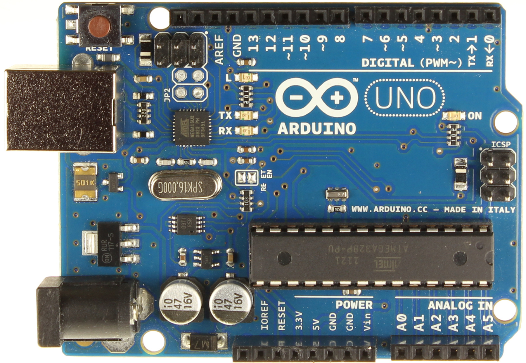
I sought out the advice of a student from last year's class who suggested that it might be easier for me to play around with the Arduino Uno to just get a sense of the dumbed-down workflow and physically see how changing circuits and code effects the result. I thought this was a pretty good idea since we had an extra week due to a holiday, and this idea not only controlled for my horrible soldering but also provided a lot of tutorials.
So, I bit the bullet and invested in an Arduino Uno Starter Kit at Microcenter for $17. If for some reason you're in a future class and find yourself realizing that you don't have the electronic/programming background that others at MIT have, and you happen to be reading this page, I highly reccomend getting such a starter kit and getting used to the workflow. It helped me a lot.
Milling the board
oh the beauty of a good endmill!
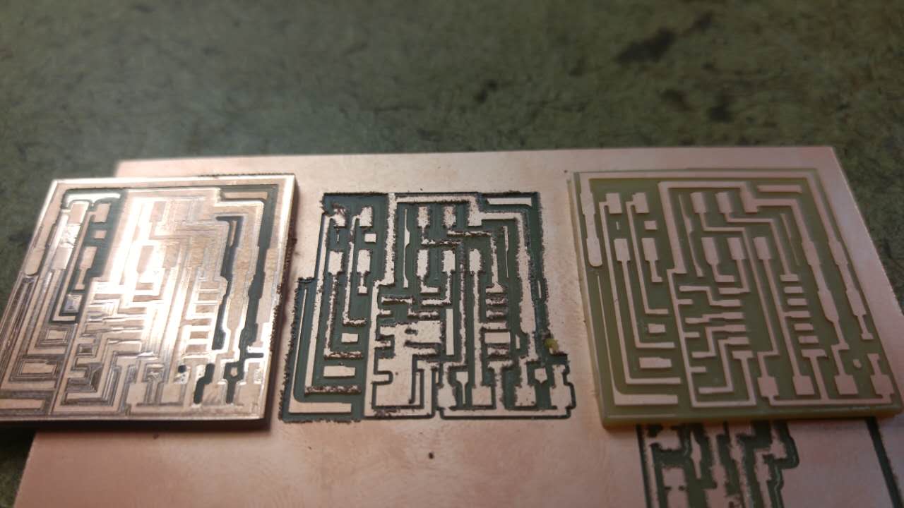
After spending a week playing with an Arduino and going through all the basic tutorials, I got to a point where I was more confident to work on a copper board. So, I decided to try a stepper motor as (hopefully) I'll be able to use it in my final project.
I milled the stepper motor board based on the fablab design, and quickly ran into 2 problems. The first was I forgot to reset the trace cut depth to .12mm so half the board didn't get cut out fully. The second was the endmill I was using was pretty rough, and I ended up with a nasty looking board. The third time was the charm with a clean board from a brand new endmill.
Collecting and Stuffing Components
don't drink coffee before stuffing
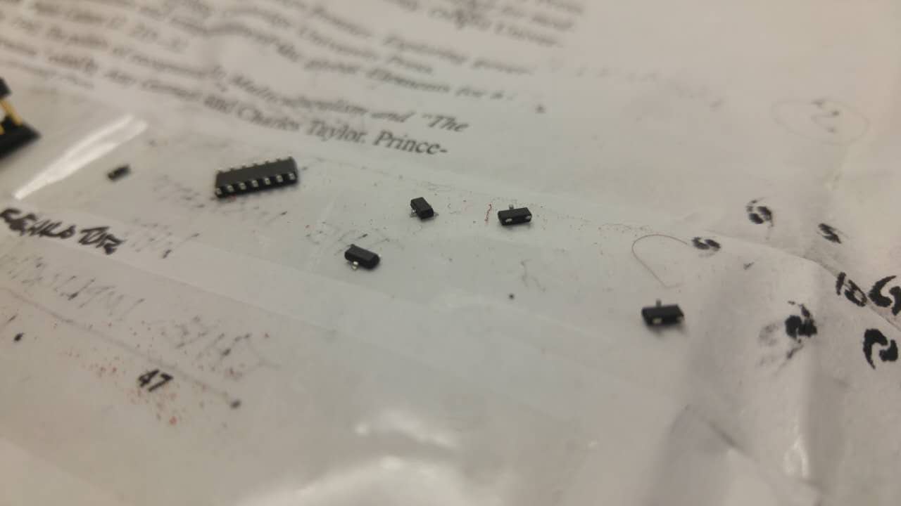
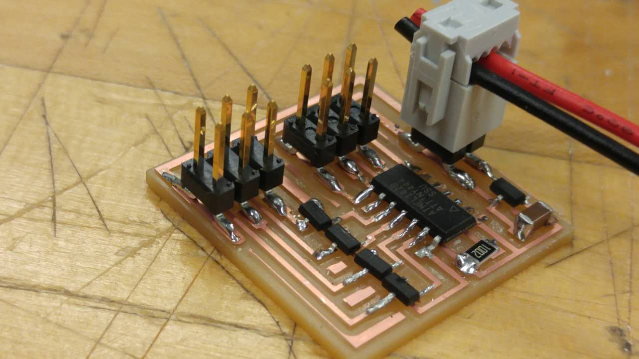
I wasn't too sure about the notation of the components that were on the stepper motor board, but a quick check in with the class via email helped me figure out that "IC2" meant a 5V regulator (which essentially ensures that the microcontroller is gettng 5V from the 9V battery) and a the "T#N" referred to the 4 30V mosfets (which the arch shop was out of).
The shipment of the mosfets came in a few days later, and I set to stuffing the board. Knowing that soldering was something I still haven't mastered, I tried my best to get some nice shiny, smooth soldering but the 2 coffees I had before hand proved to make that pretty challenging.
Checking the circuit
The dreaded "rc=-1" again
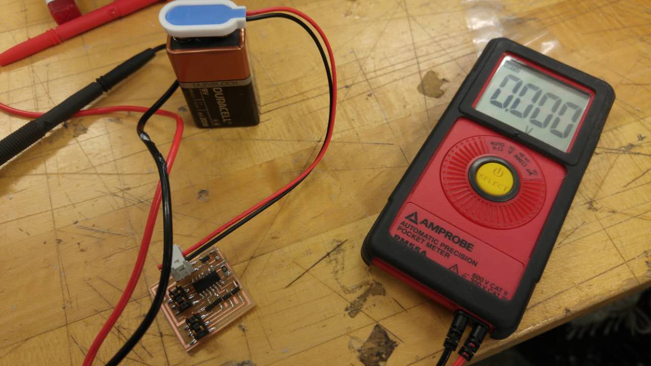
After stuffing the board I was excited to get it programmed. Unfortunately, I plugged it in and started to program but kept getting the rc=-1 error. So, with Chris' help I went back and checked the board and found the regulator was not putting out the 5V that it should've been. In fact, I had somehow soldered on the wrong component and it wasn't even a regulator.
Luckily I had milled a 2nd board which Calvin was deftly soldering withi a steady hand. When he had finished stuffing, we found that everything was in working order.
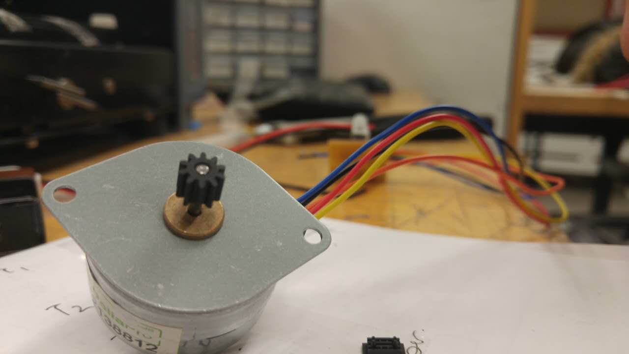
Figuring out the motor wiring
which color...
Unfortunately, the Arch section's stepper motor was different from the stepper motor that is in the Output Device example. This stepper motor only had 5 wires and the wires were all different colors than what was labeled in the schematice.
So Calvin and I looked up the datasheet for the stepper motor in the Arch section, and found that the orange wire was more than likely the voltage wire that Niel's diagram had being two wires. The other four wires we showed to the TA who said she wasn't too sure, so we kid of gave it a good guess and clamped the wires down in a header and attached a 9-volt battery ($7! and not supplied in the section).
Plug it in and go!
...and jiggle a little
The good news was that the motor moved when we plugged everything in meaning that the microcontroller had probably been programmed correctly.
The bad news was that the motor didn't rotate 360 as I expected it to. I attribute this to one or both of two options: 1) We got the wiring wrong, very likely; and 2) The data sheet for this stepper motor says it's a 7V motor, but our regulator was only giving it 5V.
That's all for this week. I feel more confident in how this all works, but still a long way to go...