- fab@fab-desktop:~$ dmesg | grep tty
- [ 0.000000] console [tty0] enabled
- [ 1.115994] systemd[1]: Created slice system-getty.slice.
- [ 1.116007] systemd[1]: Starting system-getty.slice.
- [ 3.437178] usb 1-3: FTDI USB Serial Device converter now attached to ttyUSB0
- [ 3.437315] usb 1-4: FTDI USB Serial Device converter now attached to ttyUSB1
- [ 842.532740] ftdi_sio ttyUSB0: error from flowcontrol urb
- [ 842.532792] ftdi_sio ttyUSB0: FTDI USB Serial Device converter now disconnected from ttyUSB0
- fab@fab-desktop:~$
redo step_2: Milling & Soldering the board
I was not very satisfied with the way I have produced my board because when I tried programming it, terminal kept giving hardware errors. Thus I have decided to not only mill+load the board from the top but also to check the eagle schematic in order to make sure that the connections are correct!
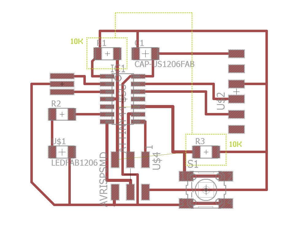
after a quick match+check between the schematic view and the board view of my circuit of Eagle, I have realized that I misnamed 2 resistors that have the identical resistance (10k) which is probably why I though the naming would not matter. Well, it certainly does!
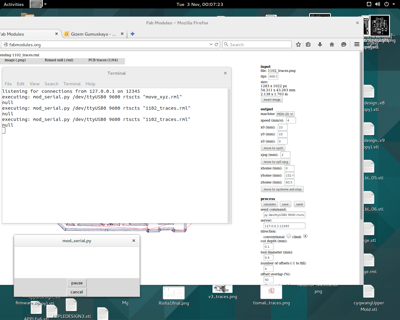
after renaming the resistors and exporting traces+outline of the board; I have imported the traces.png to fabmodules and set the settings as I always had. However the terminal was strangely giving me the blank mod.serial.py window above. I have checked all the hardware connections between the modela and fabmodules but the problem sustained.
after struggling for more than 2 hours, Dan Chen helped me realize that there was another FTDI cable plugged in to the serial port and thus the fabmodules was trying to talk to that FTDI cable which was preventing modela to properly converse with the fabmodules. we used the piece of code below to diagnose this:
after unplugging the unnecessary FTDI cable, modela was happily running!
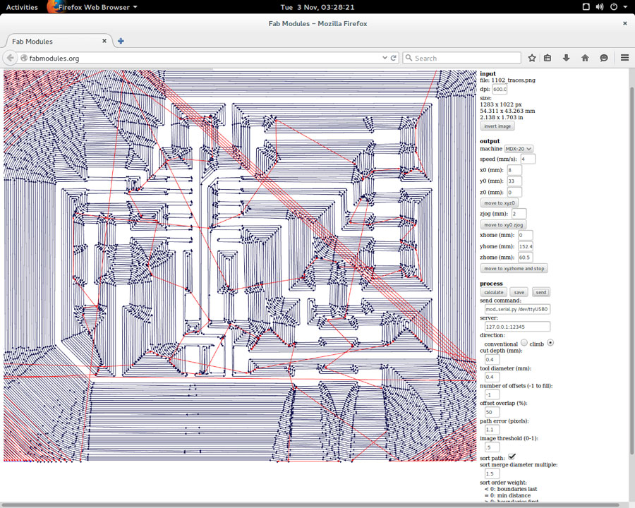
at this point, I have decided to get rid of all the unnecessary copper on the board. To do do this, I have set the 'number of offsets' to -1 on fabmodules which ofsetted the toolpath until the borders of the board as can be seen below:
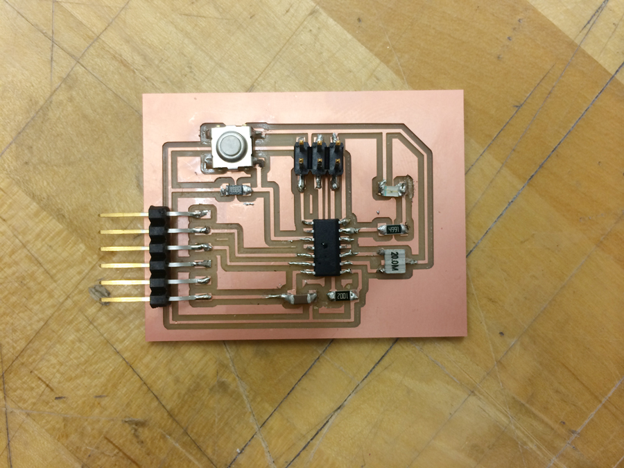
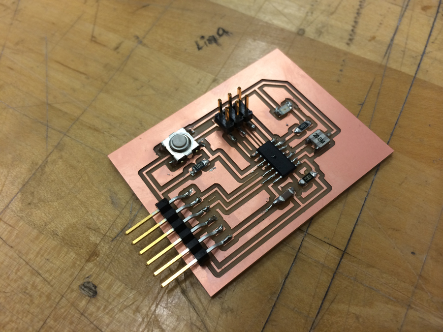
the board came out fine
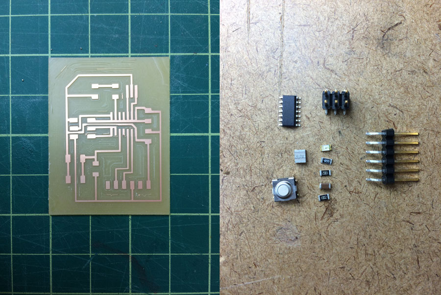
then it was the time for mounting the elements of the PCB
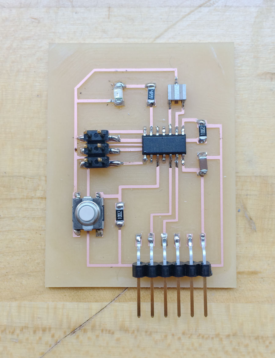
important: pay attention to the LED's direction! I had the direction problem with my diodes during fabISP production in week3 and had promised myself to get alarmed while soldering diodes from then on. Well, one should never forget that LED stands for 'light emitting diode ! Again, anode should be soldered to the ground because current flows from anode to catode.
step_1: Designing a circuit on Eagle
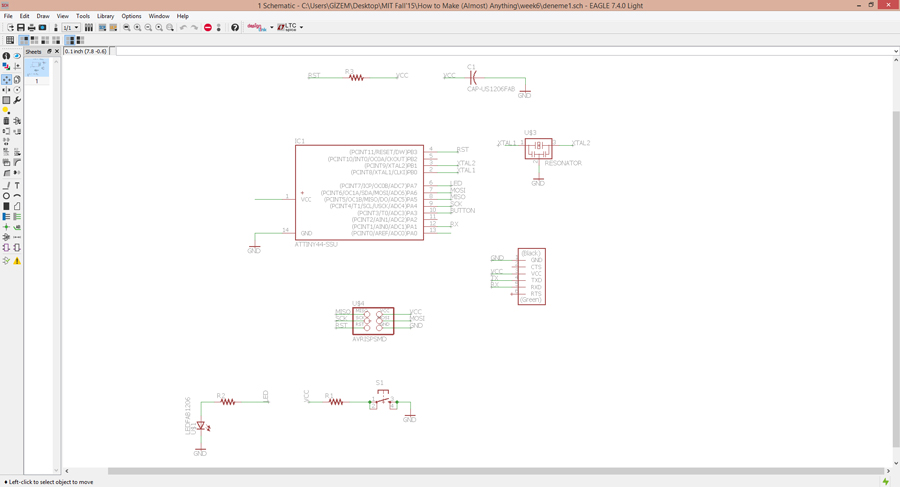
I have started by placing members of the board to the workspace:
+fab/attiny44-ssu
+fab/res-us1206fab
+supply1/+5V
+supply1/gnd
+fab/resonator
+led/ledsmt1206
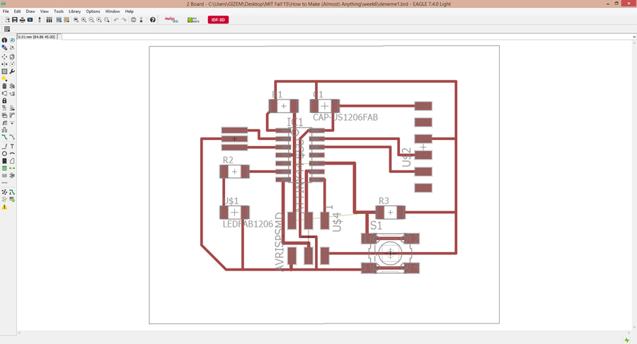
Then made the net connections at appropriate places and switched to the board view to connect the members to each other.
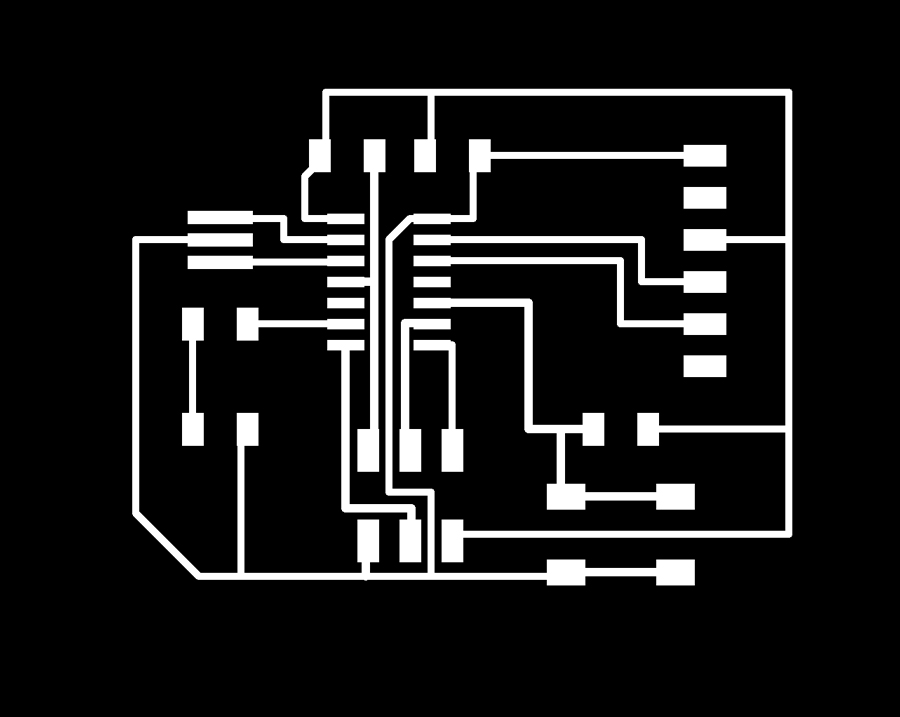
exported the traces in monochrome to mill
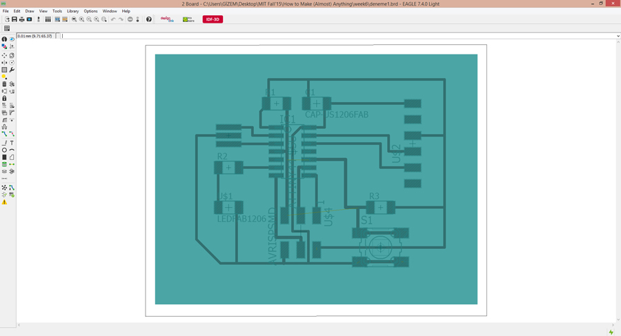
Then draw a rectangle around the traces on layer 48 ("milling") which helped me to export my outline
step_2: Milling & Soldering the board
Thanks to the third week's assignment, I was experienced with milling the board
next step: programming the board in 2 weeks!