Computer Aided Design
I am going to attempt to cast a 2 part mold for this assignment. The geometry I used was a pipe so I would need to mill a mold for the exterior piece and interior pieces of oomoo and then attach those to cast the rockite.
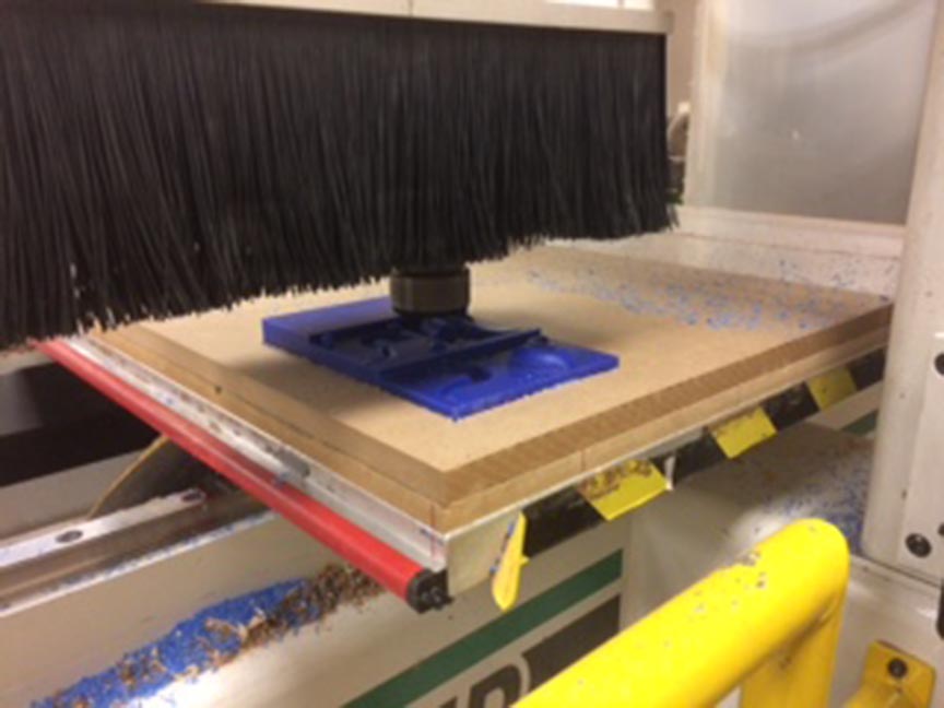
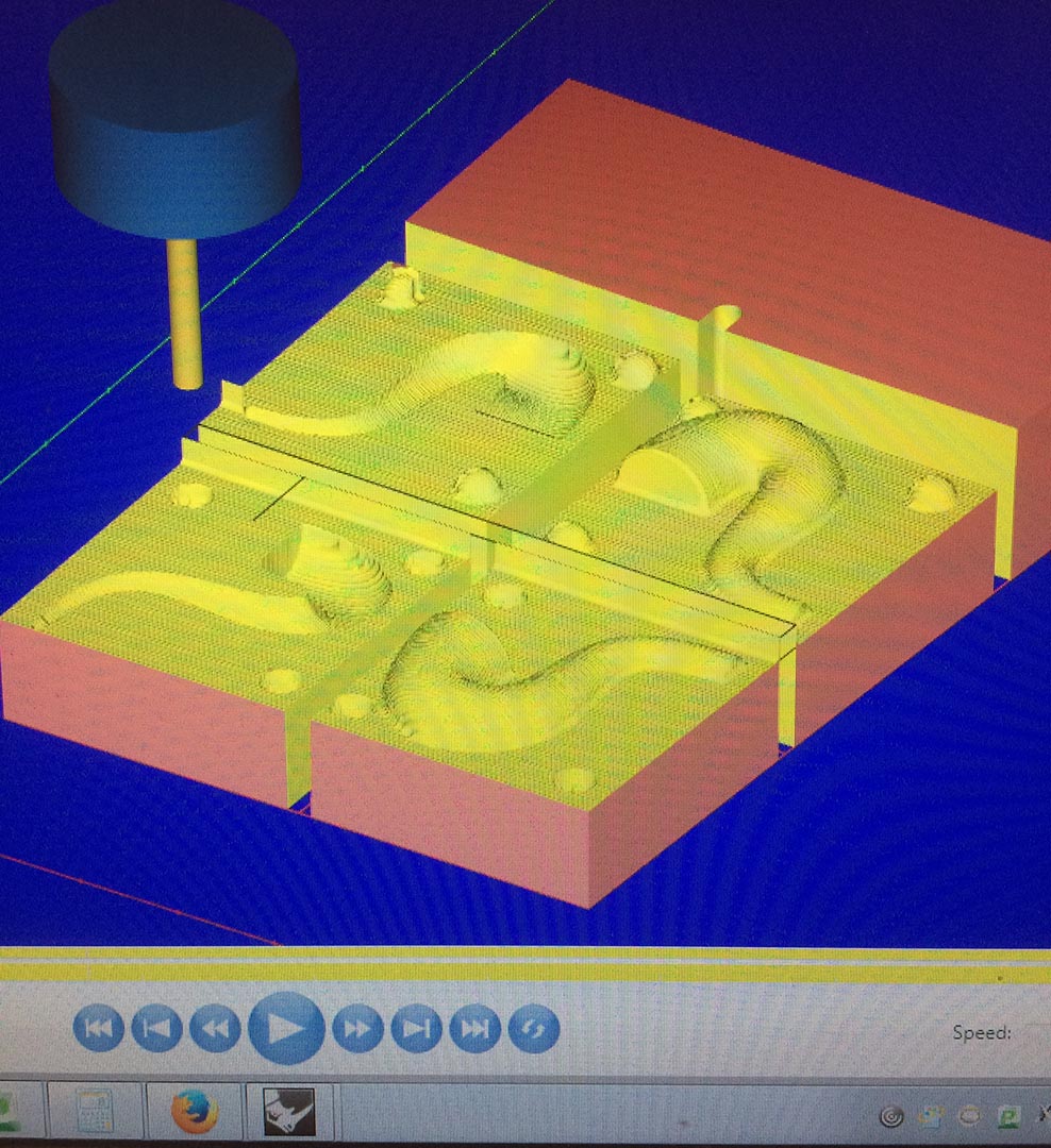
First step was to set up the geometry in MasterCam.
Next up was to play with the settings and do some testing on speeds and feeds. Chris Dewart hadn't cut this stuff so he told me to try a few speeds feed rates and let him know what was working best.
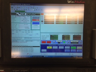
While milling the wax on the onsrud I tested a few different settings to see how it would cut and tried to find the best results.
Final Settings
Rough Feed Rate 600 @ 16000 rpm
Final Feed Rate 300 @ 16000 rpm.
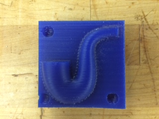
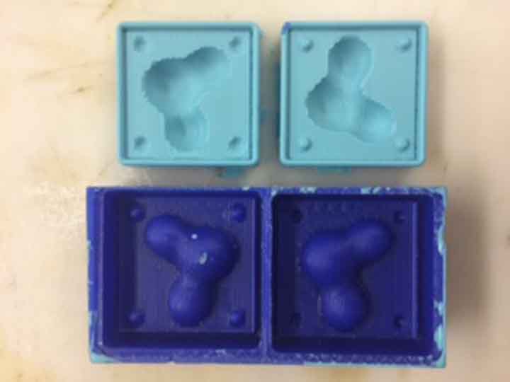
The molds came out okay but there are some issues with the registry holes and the wax needing to be sand. At the same time as I start to fix these I come up with an idea. Can I manipulate my geometry from 3d Scaning and test the result in casting to see what the change is and if one is better than the other. The mold should be resuable so one it is made it theory you could reproduce blocks quicker than 3d printing them.
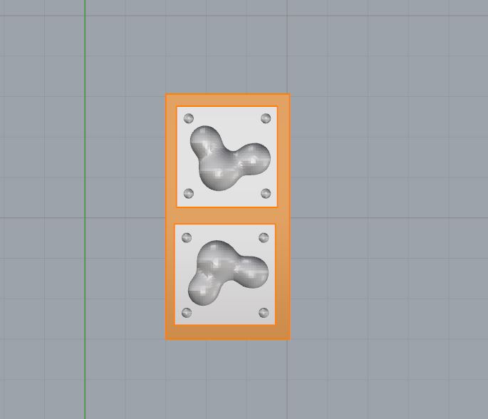
Geometry for exporting to MasterCAM and the fate of the wax and oomoo casts.
Re-Usable mold (above.) I had to modify the geometry slightly to avoid any undercuts but that was just quick adjustment in the grasshopper defintion. Next up is casting.
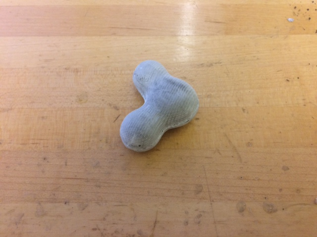
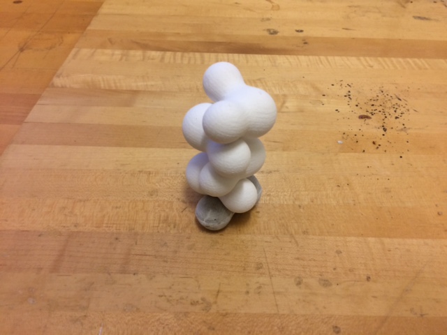
The result is pretty good, however the machining paths are clearly visible. In this case I actually like that because the machining lines are similar to the contoured lines used to represent the geometry anyway. It makes a pretty nice effect I feel. I will now test to see if it fits within the tolerance of the other system of 3d printing blobs.
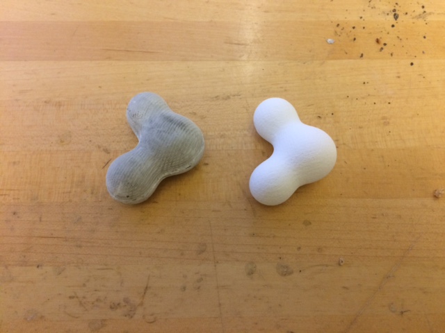
Side by side comparison (top.)
Rockite module in the 3d Printed wall (bottom.)
Now I could theoretically have the mold forever and be able to crank these out way faster ahn the typical MIT 3d Printing job.