Input Devices
This weeks assignment is getting into input devices in terms of design, production, and reading the input. And while
it is not part of final project I want to use the PIR motion sensor because I have some future ideas to incorporate this into the lighting at my apartment so I want to get some experience while I can.
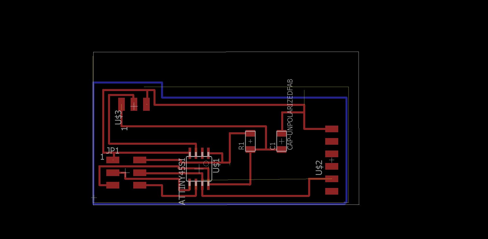
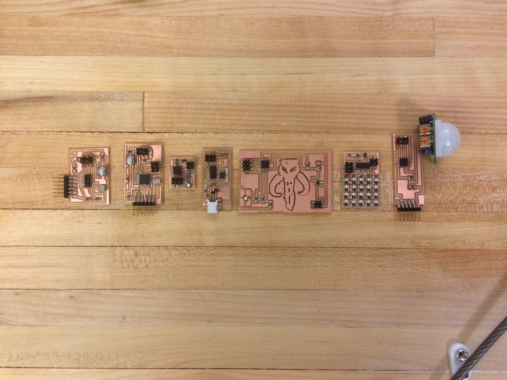
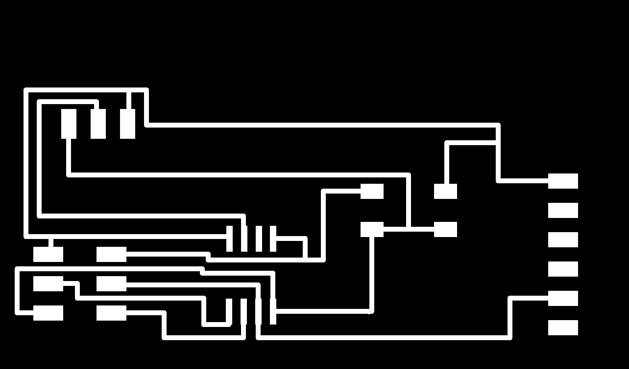
Here is my board design, it is pretty simple with an ATTINY 45, a header, ftdi header, a 10k resistor, 1uf Capacitor, and the padding for the motion sensor. I had issues finding this part in the classes library so after talking to Nadya she decided to just show me how to create my own symbols and packages to create a simple 3 header pin.
The process itself is actually pretty quick you just go into your library and and a new part, then draw the pin heads, connect them, and you can use them in your library. Alternatively there are some other 3 pin symbols that I believe are close to what are needed anyway.
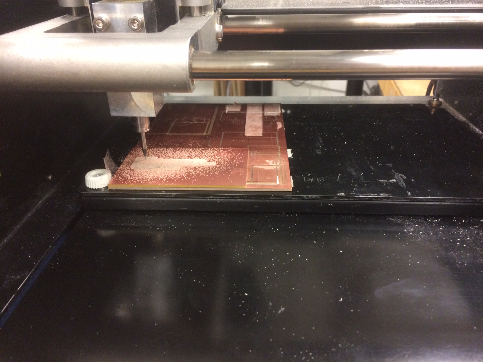
Traces export - - - Mill.
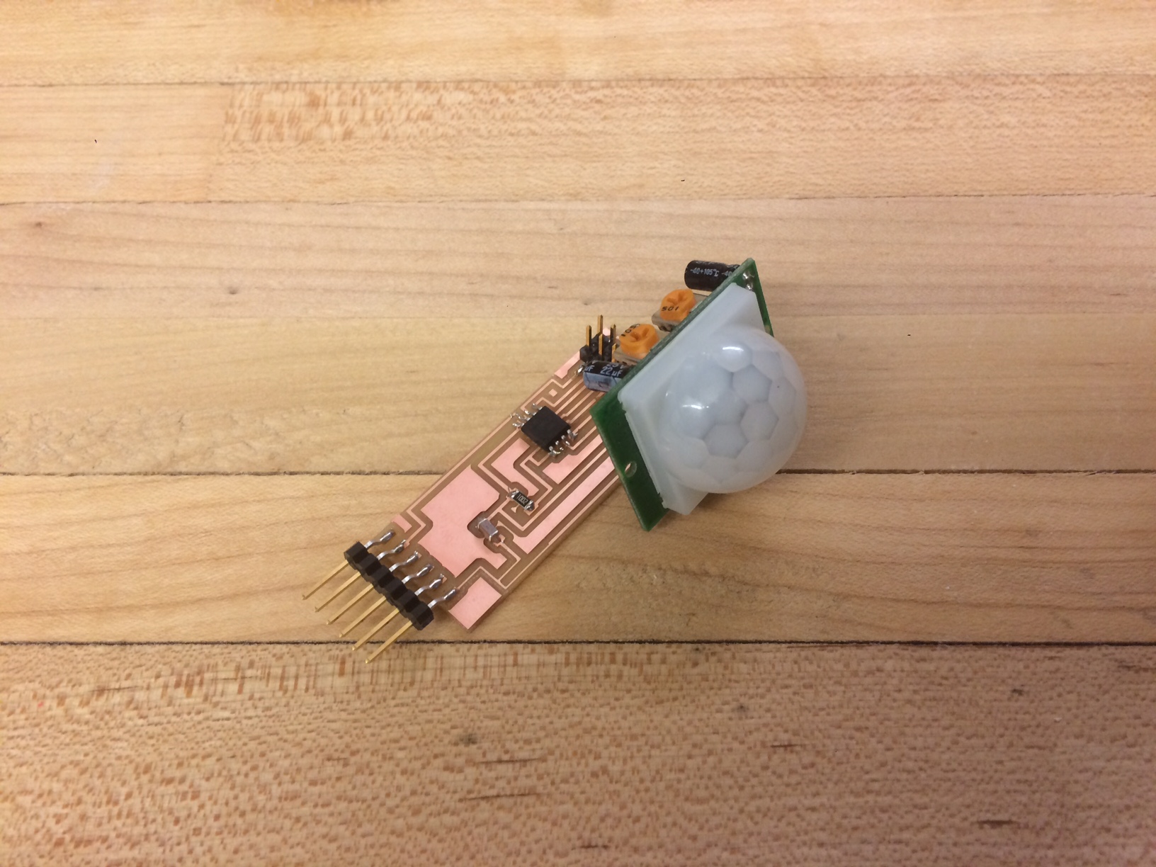
Warning, one issue I ran into was that the length of the pins had mine running pins perpendicular to and touching two of the traces.
This wasn't a hard fix or a big panic but if it can be avoided it will be useful. I just added a lot of solder to hold it up and hovering gently over the traces so they are fine.
Update: Maybe I should redo this, while trying to program the TA and I accidently snapped of the motion sensor so either I resolder it or redo the board.
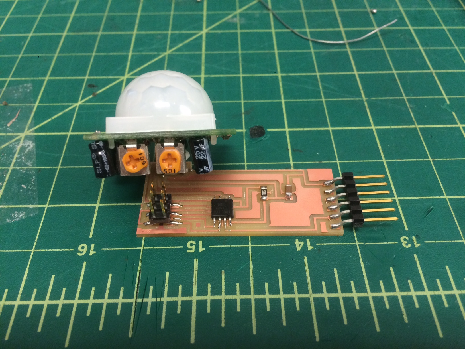
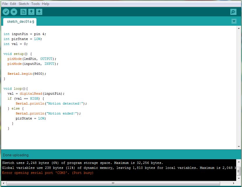
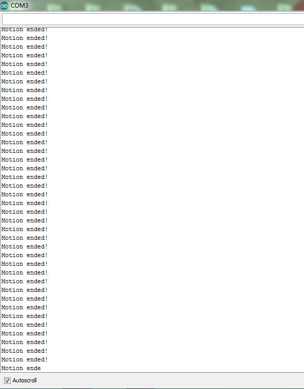
I have now updated the board and will be attempting to burn an arduino bootloader on to communicate and read the HIGH/LOW input. So Iwil set up a quick arduino sketch that is just meant to read when it gets a high input and will then print "Motion Detected" and when motion stops it will write "motion ended"