Group Project/Lazy Bartender
The group project is going to be a "lazy bartender." It will be a plate that spins on a stepper motor to different positions, the move up in the z axis with the steppers we made in the first part of the group project. We have divided into 4 main groups, Rack Team. Circular Mechanism, Mechanical Hinging, and software.
I am in the circular mechanism team. The first thing I did was talk to Calvin and Nadya to determine if she had a polar axis motor or if we could just use a stepper motor, which we have to figure out how to work into the Gestalt system. Our group composed of Liz Schell and Anthony Kawecki have met and organized our plan to move forward. After recieving the Rack Team's initial update I took the low res model and updated it with the stepper motor in place.
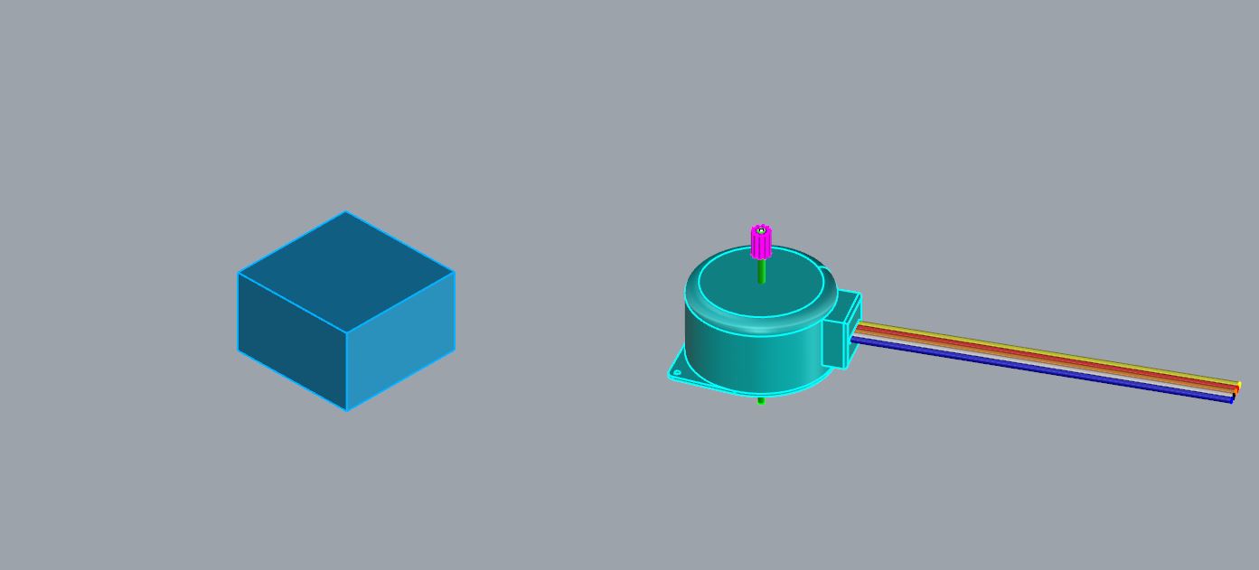
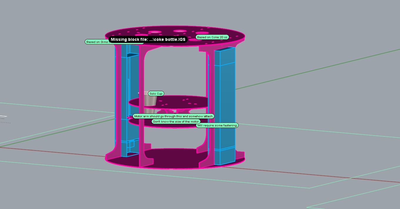
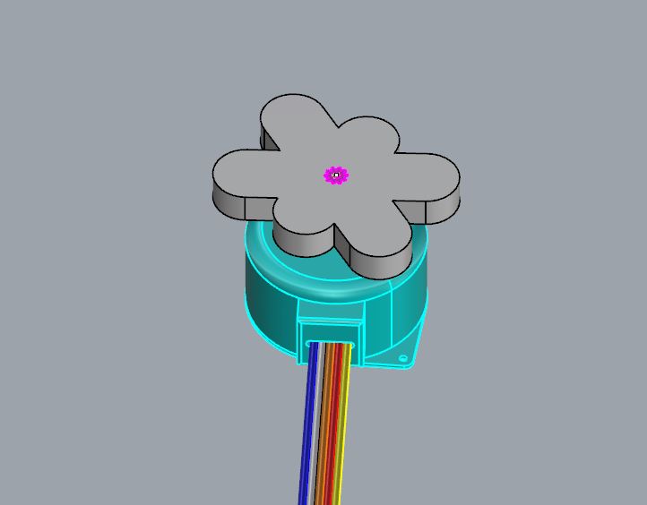
On the left is Rack Team's initial block for the motor. I updated it to be a more precise model which will allow us to design all the connections and make sure there are no issues in the design.
It actually has been kind of relaxing to do some small 3d modeling after working on the ridiculous 50 million square feet of urban planning happening in our studio work... After updating the design itself, I went through and modified the connection mechanism of the motor. For now that just consists of intersecting the geometry to cut out the profile of the motor allowing it to spin the plate directly. The only issues for this depends on if the material is strong enough at those thing moments of teeth to resist getting torn up the by torque of the motor.
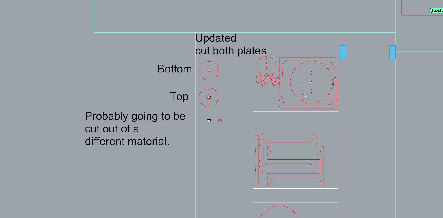
Small Modifications to the cut file. We will discuss this at the next meeting.
Update:
After our meeting, it was decided that we only had to do some small modifications of the design and we are all on the same page on moving towards the final design. We will be finalized the design and production by next Monday (11/30/15) This will allow us to send it to the software team a week and half for them to do the coding precisily and create the final product. Personally I have to update the mechanism which will result in adding a new piece that grips the stepper and distributes the load from spinning across larger teeth of the plate. We are now using two layers one which will allow the larger mechanism of the stepper to sit on, and the second will have larger teeth to spin the plate. We have also decided to add wheels on the plate to reduce the stress on the motor. Design updates and drawings to come soon.
I have also talked to the software team and we need to figure out how to design the board for the stepper motor into Gestalt system.
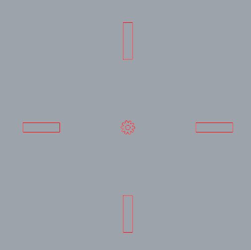
I have added an extra piece that will attached to the stepper motor that will spin the plate. We can make this out of a stronger material if need be to prevent breaking. The longer teeth will distribute the torque among more area and reduce risk of breakage compared to the tiny teeth.
I have reflected this in the cut files by updating them and will chat with Rack team and make sure this is all set.
Update:
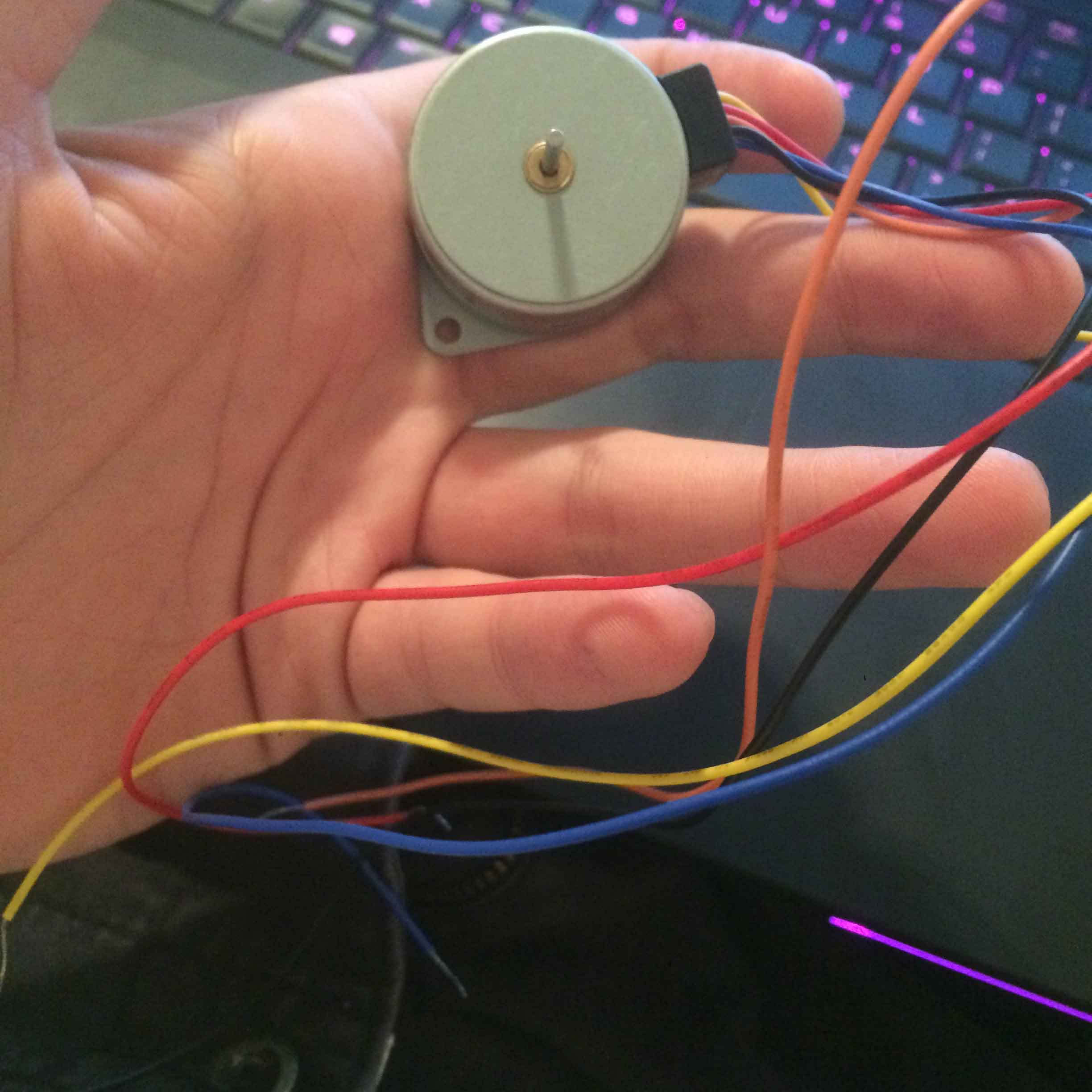
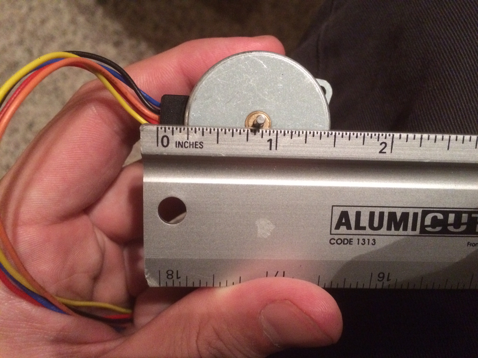
After meeting with the group we realized that we needed to use a different motor to connect to the Gestalt System, luckily Nissia had one she could bring in.
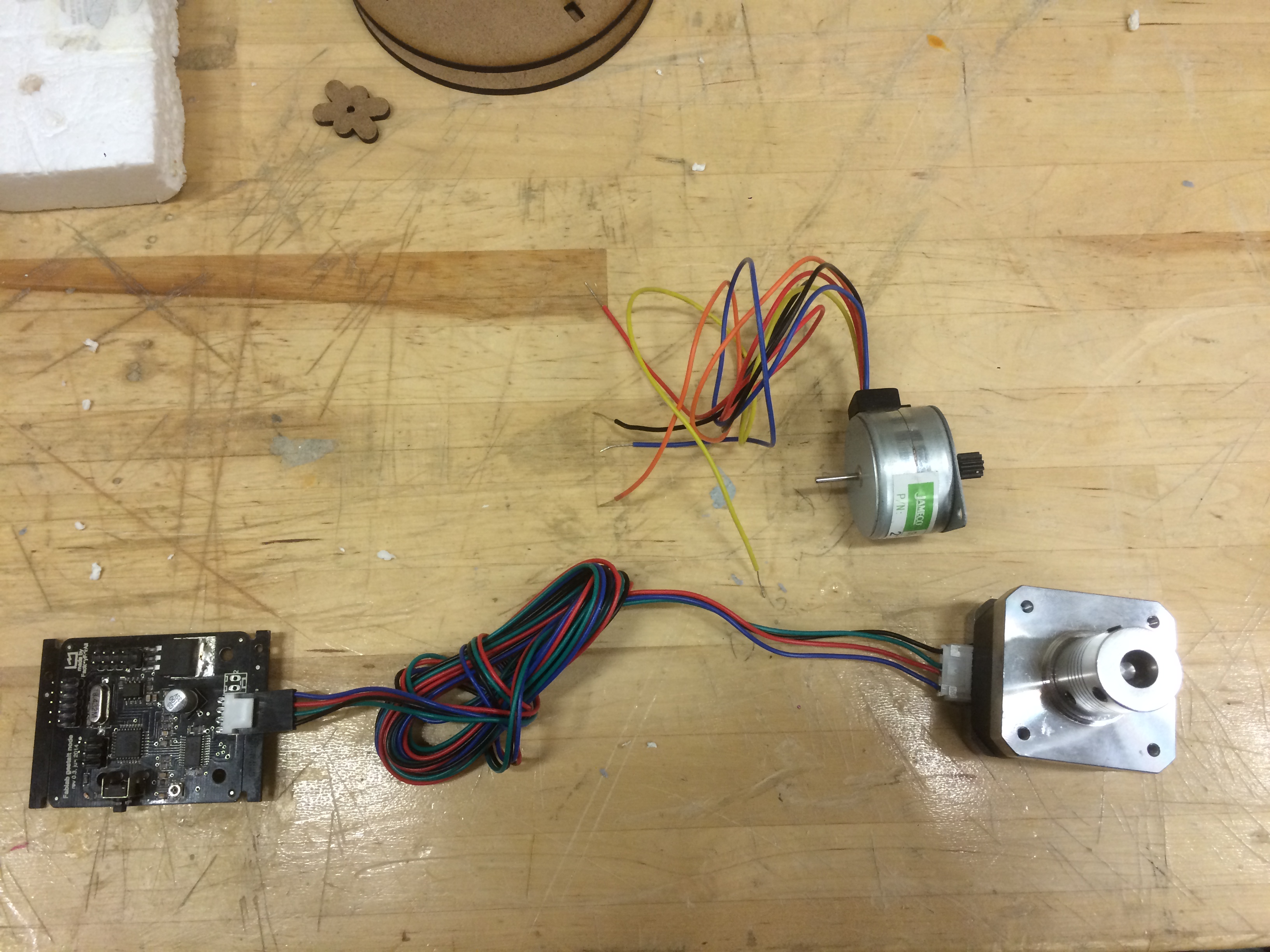
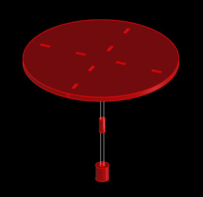
With the new motor, we needed a new way to connect it to the spinning plate which could be done either laser cutting and glueing a few pieces together or just buying a little tube with an inner diameter of 3/16". The assembly would look something like this:
After modeling and laying out some more laser cut files, I have sent the updates and suggestions to the rack team and should conclude my work on this portion. At the same time I spoke to Nadya for the software team about how to program the polar motor in the gestalt to see if there would need to be a tranlation from linear to polar or if she had a better idea of how they should go about doing it.
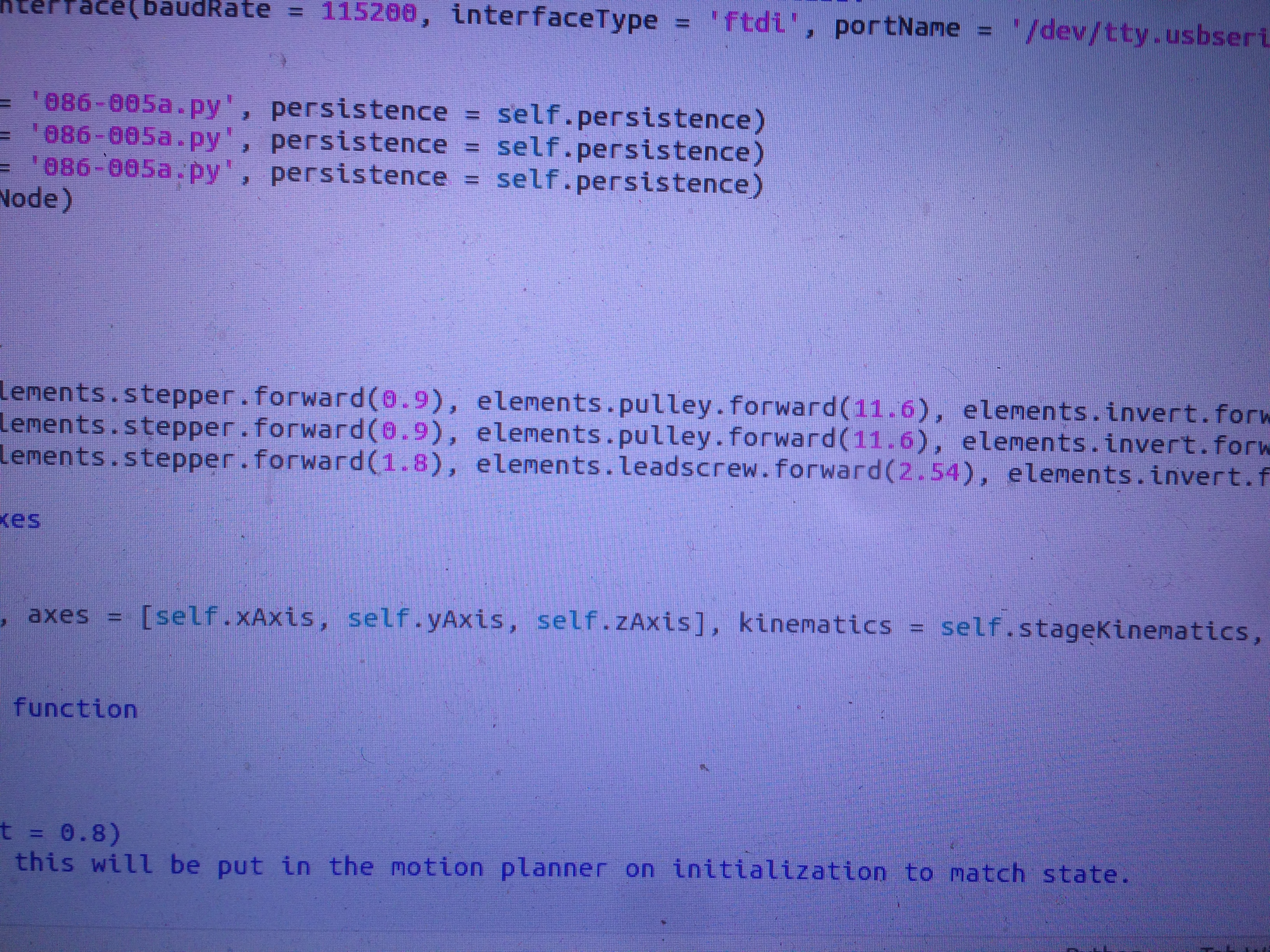
She showed us you can go into the machine elements and instead of using elements.leadscrew.forward you could use something like a elements.pulley.forward. The only issue was that it was using millimeters which is okay but that you could also change it to angles if necessary. However, the time it would talk to change to angles is probably longer than just testing the millimeters to angle distance in real life by testing it.
Update:
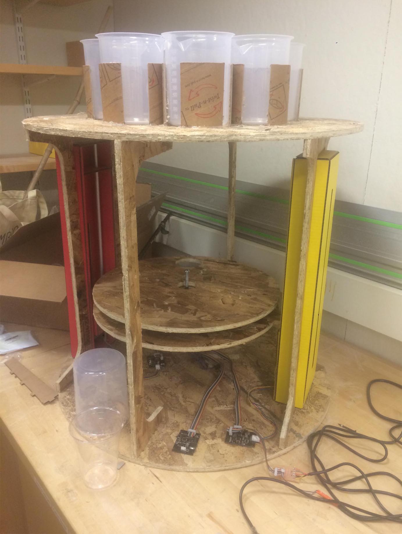
Today, I'm not sure what day it actually is anymore. we put together the rotating device to some degree of failure. The rack team used 1/2" plywood and cut the rotating piece out of that so we tried putting it all together.
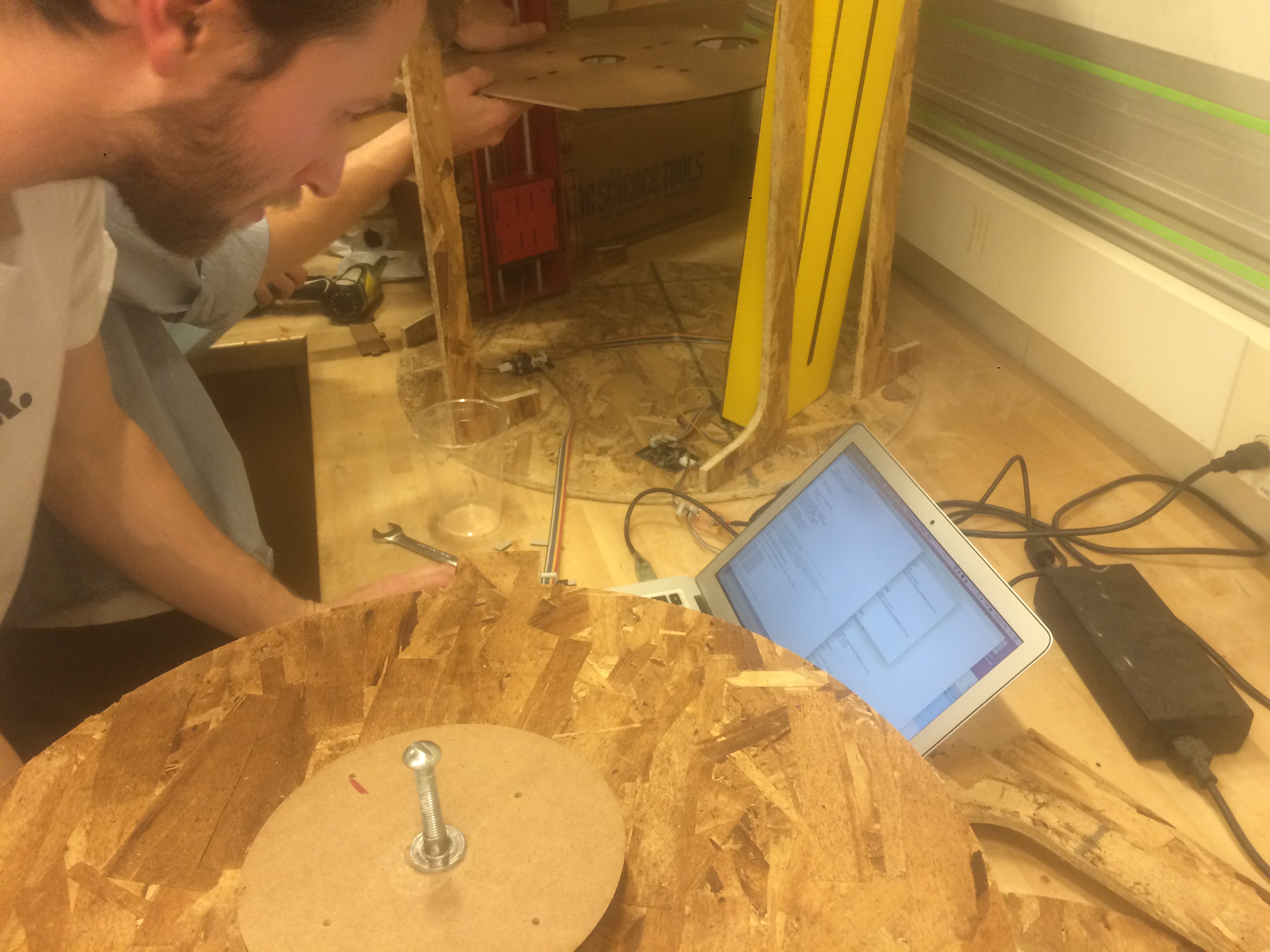
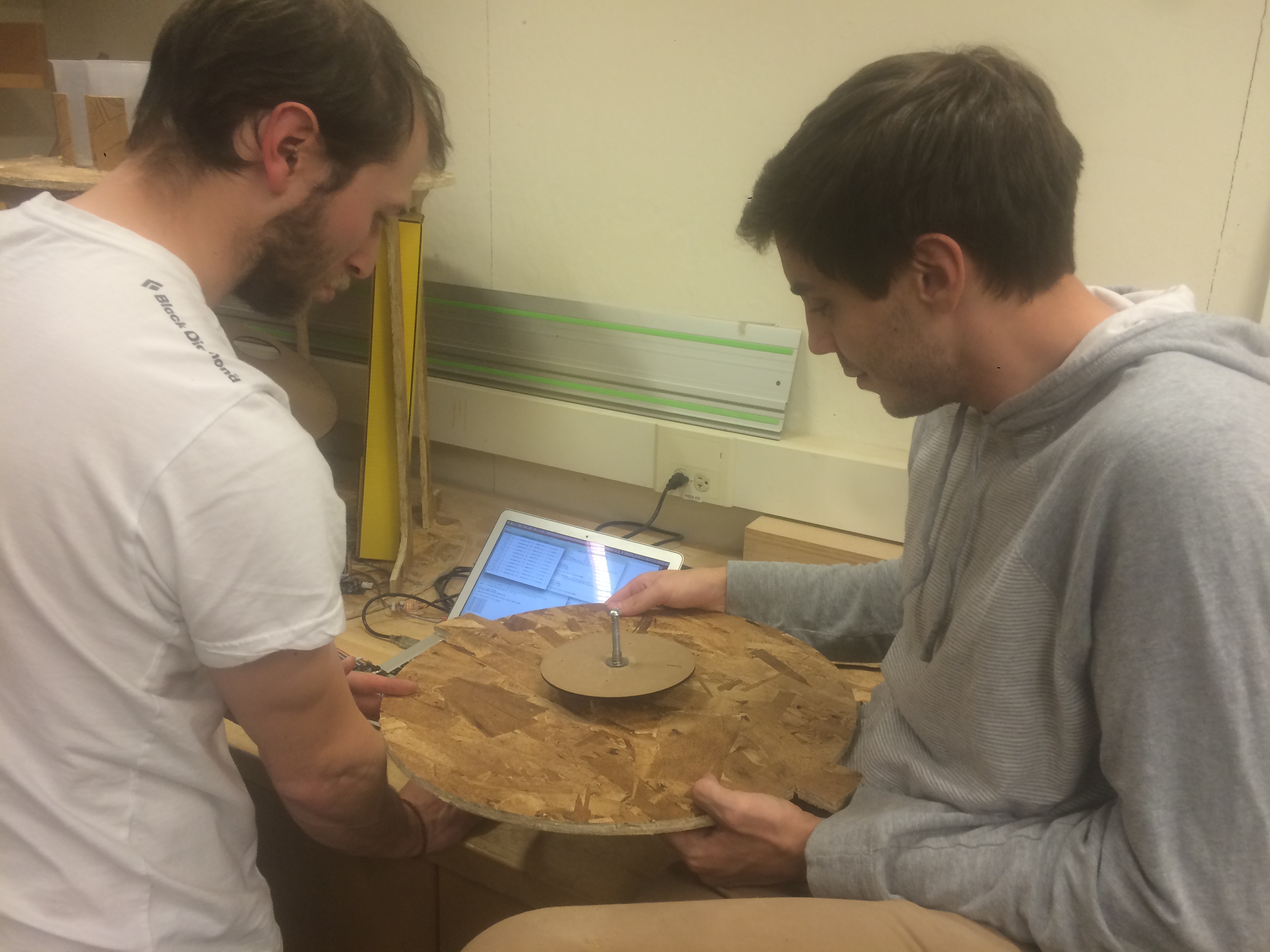
After Testing it out, which you can see the video here:
Here, Chris and I are testing to see if we remove the plywood if the motor would spin, which it did. This meant it was definitely the wood and we needed to make a new arm. We realized it was too heavy for the motor so it prompted us to go over how to change the the arm.
Sam quickly set up a laser cut file to reduce the spinning platform to a singular arm that would have a caster underneath so it was lighter in terms of volume but also material, we switched back to 1/8" Masonite.
We have all the parts working its just a matter of intergration now.