Final Project
My final project continues some research I have done with tranlucent concrete. I wanted to use it, but take it one step further by embedding electronics into a facade that was made from it. What is it?
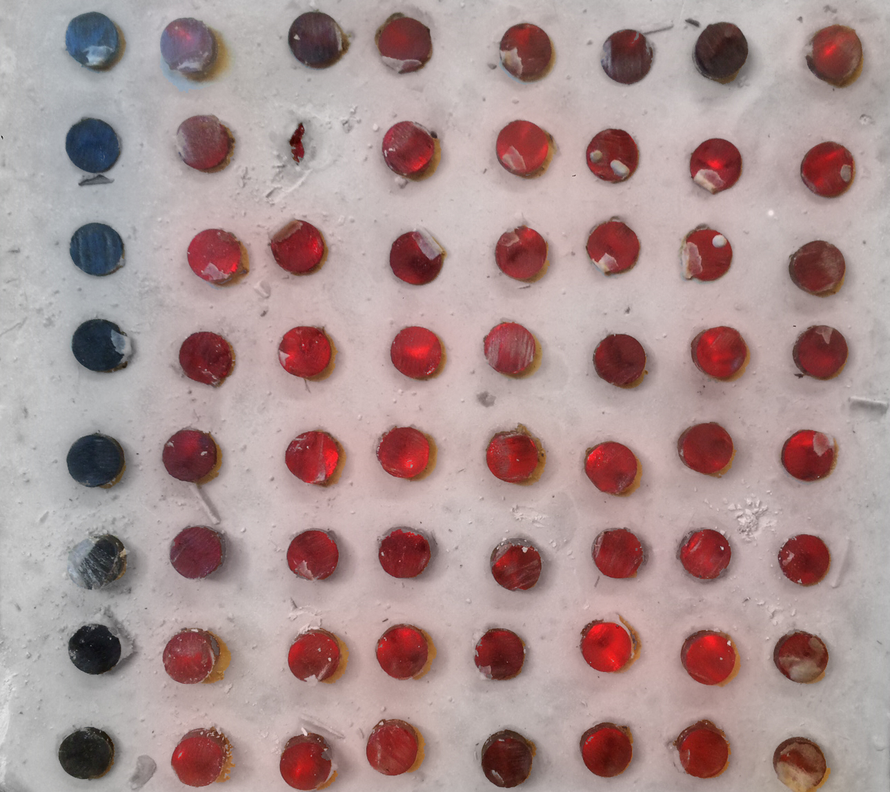
Here are some samples.
![]()
![]()
It has been produced mostly by two companies. Luccon and LitroCon. It is made by casting fiber optic woven fabric into concrete which allows light to come through.
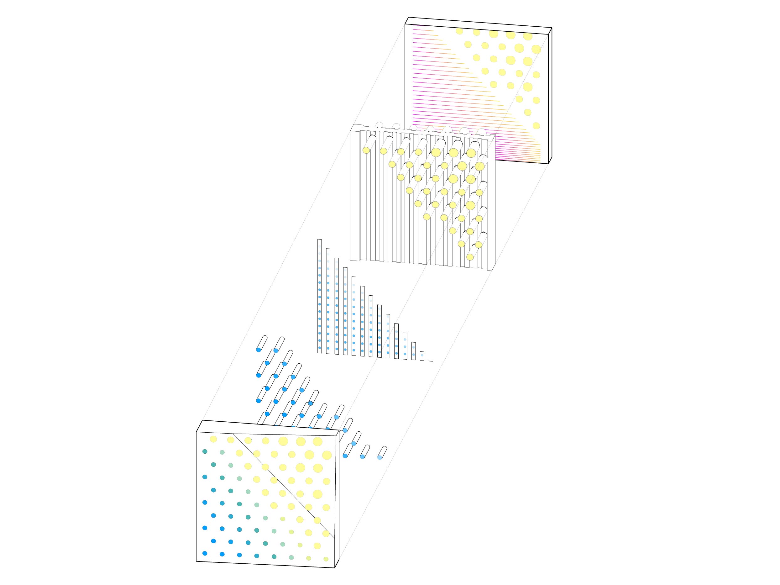
Embedding electronics allows it to become a media facade, but it seems like a light of work for just a media facade that can normally be mostly exposed electronics. However, the huge benefit is that it allows the wall to become structrural, meaning it can actually support structures and not just be a curtain wall. I will also be subsituting the fiber optic fabric for acrylic rods because of the scale. Casting acrylic and fiber optic fabric into the concrete creates a composite allowing the concrete to take compression and gain additional tension strength from the acrylic rods which are better in tension than concrete. Here is an image of roughly what the project should look like:
For the final project it will include a lot of processes from this class:
Computer Aided Design
(designing the prototype and preparing cut files)
Computer Machining
(MasterCAM and Machining the molds and insulation)
Molding and Casting
(Producing the Molds and Casting the hydrostone)
Electronics Production
(
Producing a board to run the led strips)
Electronics Design
(Designing the Board)
Embedded Program
(Programming the Board to run the LEDs)
Output Devices
(Controlling the LEDs)
Composites
(Concrete+Acrylics Rods)
Process
The first step was modeling all of the molds, and the geometry that I will be making.
The next part of the process was the machining, this went pretty quickly as the translation from rhino the MasterCam is pretty straight forward.
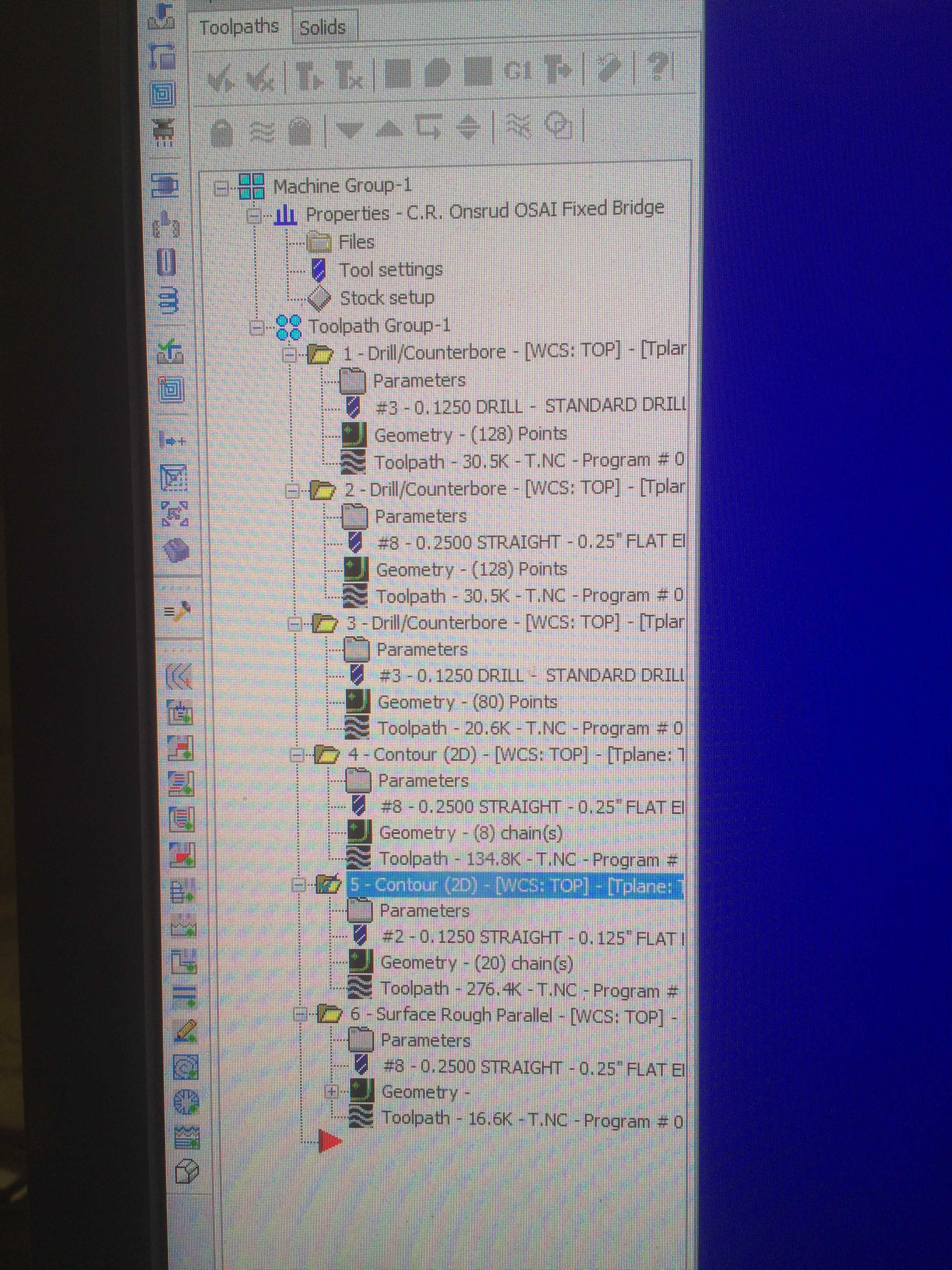
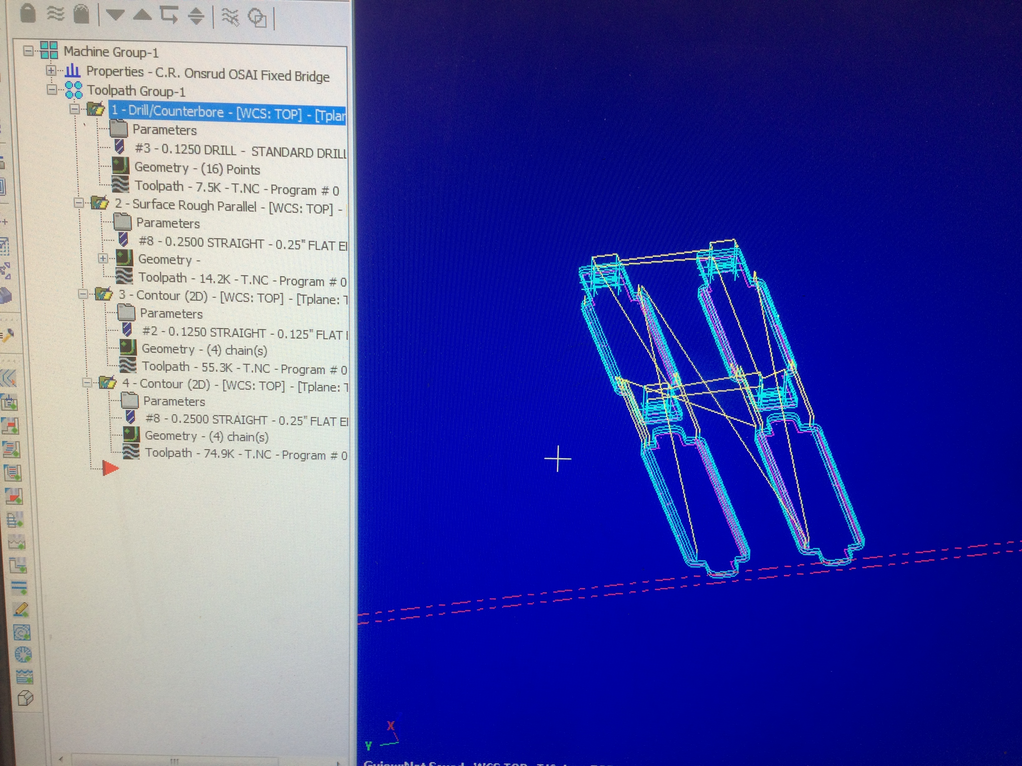
For the molds I had to set up multiple toolpaths for the best efficiency I could get.
I set up 3 drill paths, one 1/8" path that drilled the holes to hold the 1/8" acrylic rods, one 1/2" one to hold the 1/2" acrylic rods, and finally one more 1/8" path to get the corners of the press fit mold to avoid the issues of filleted corners.
I then did a surface rough for some of the tabs and interior and exterior contours based on the geometry.
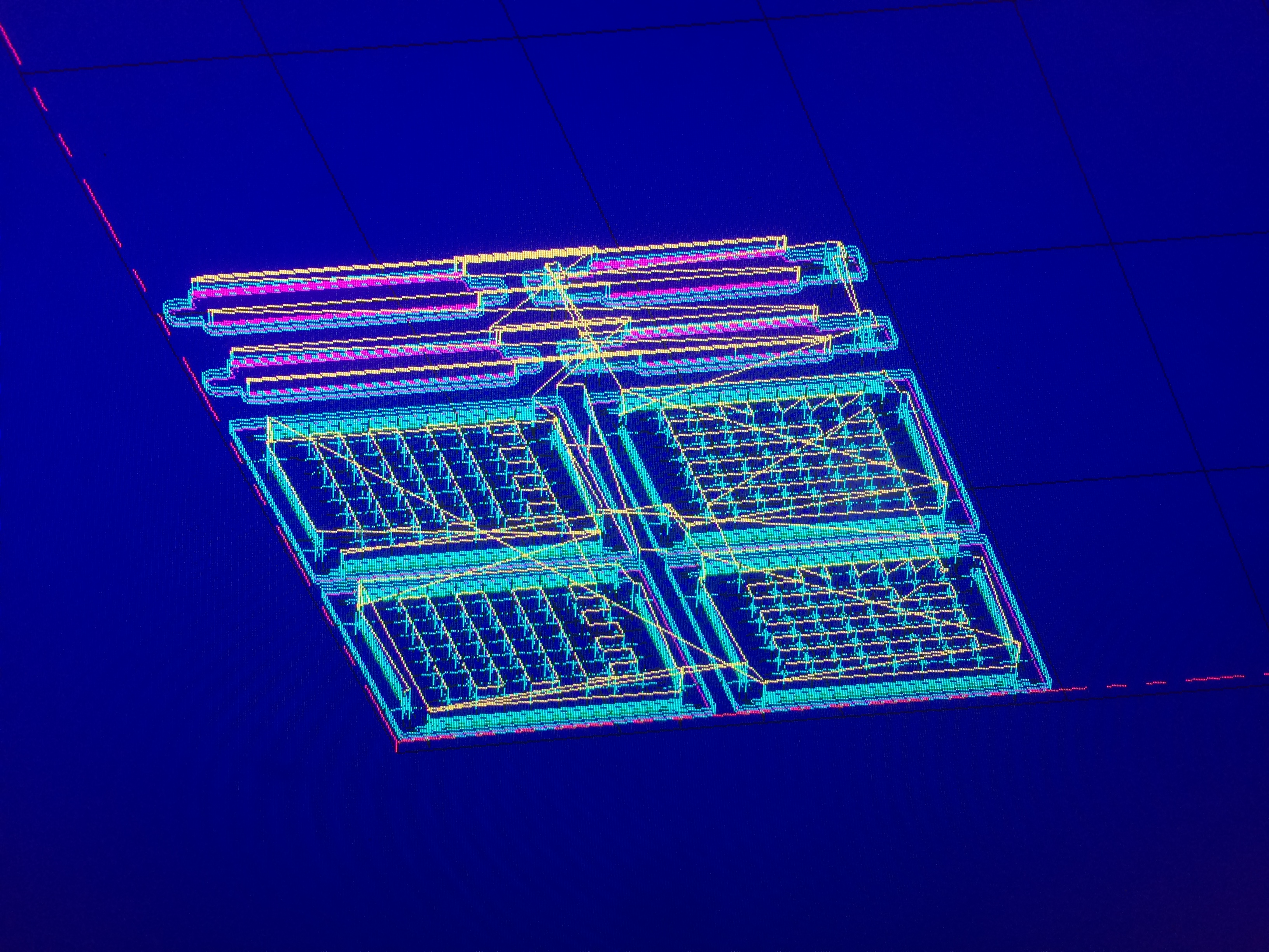
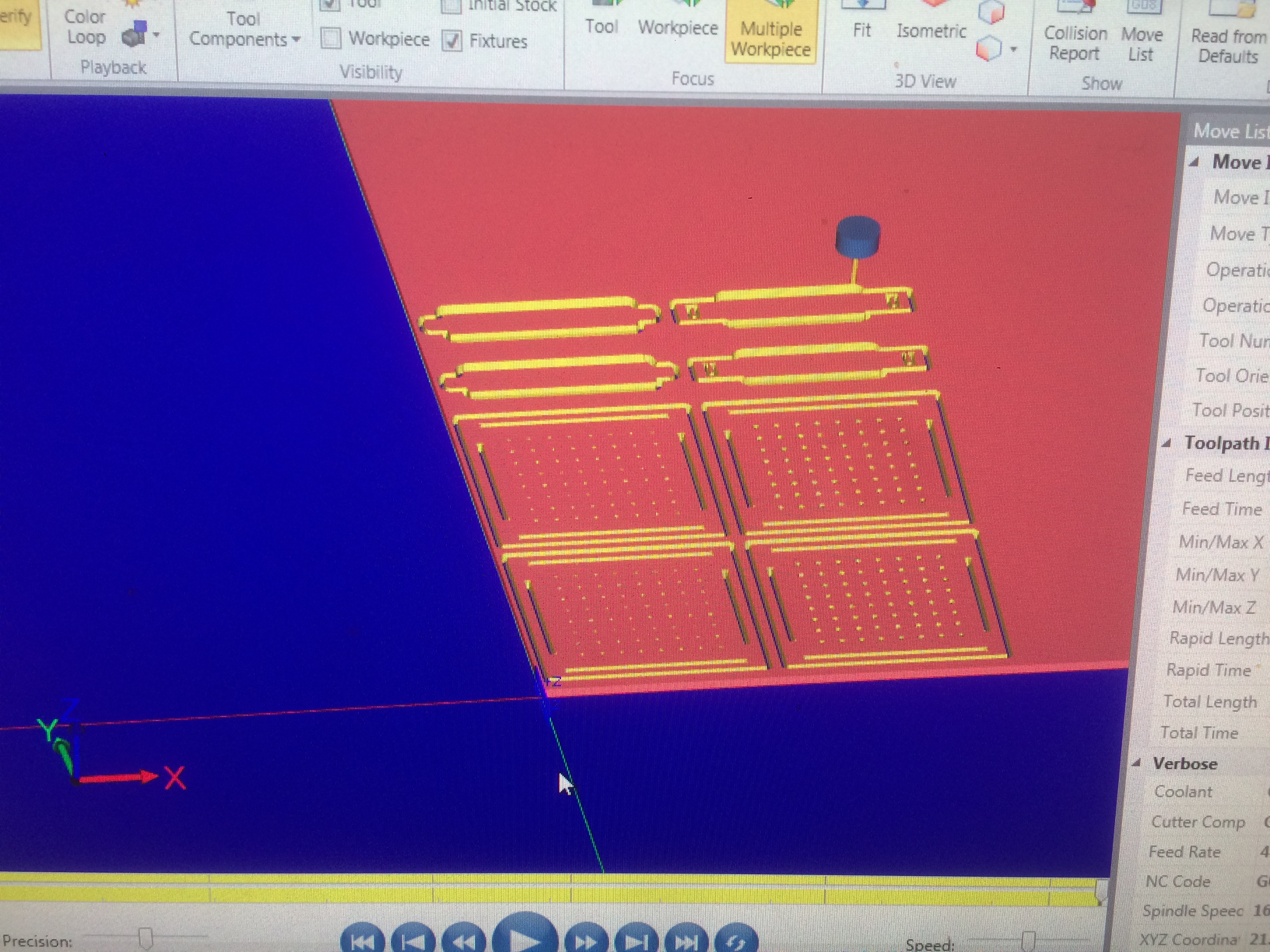
Here are the resulting toolpaths and the double checking of the job.
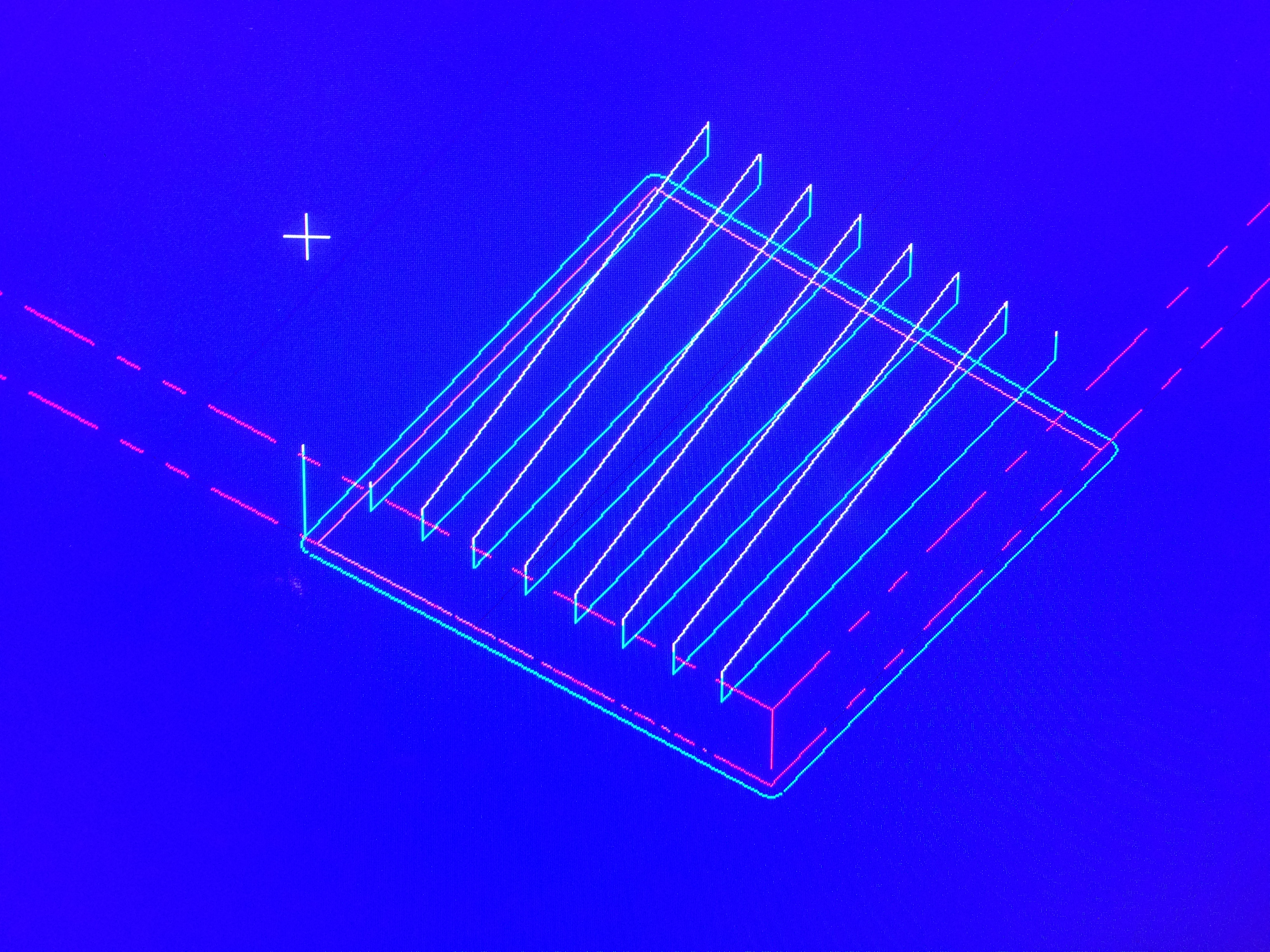
I also set up a quick file that just runs a 1/2" endmill to create strips to hold the LEDS in the insulation.
Everything looks good so I am now about to run all the jobs, which come out to an amazingly short 30 minutes for both jobs.
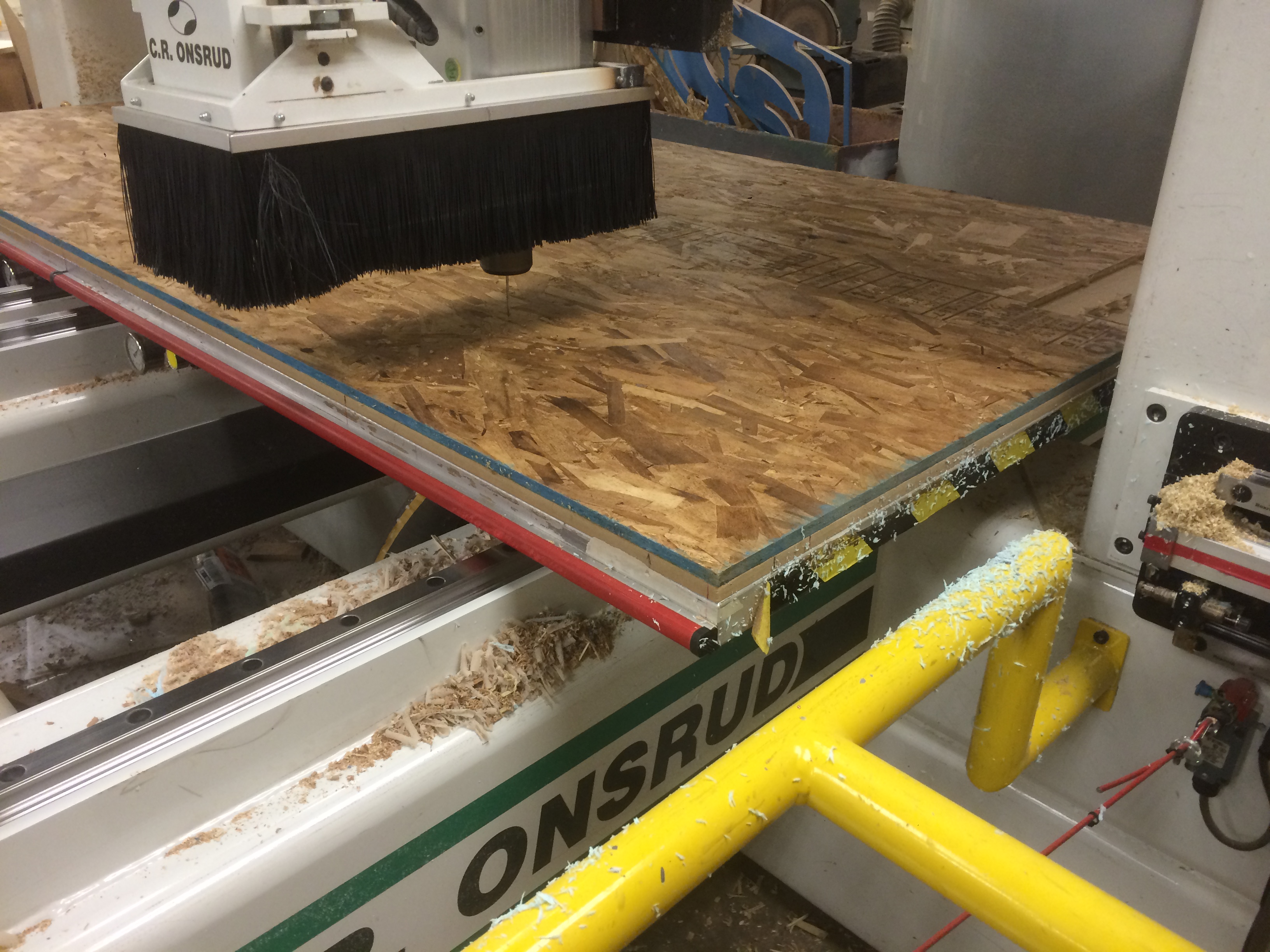
During the milling process I made one big mistake - the order of the cut paths is very important and I over looked that. The issue was that I cut the contours out first and it went to surface over small pieces that had already been cut, causing them to move around. Stupid but a small adjustment and an easy fix:
In MasterCAM I simply moved the geometry over, reordered the cuts, and re exported the g code. I left my file on the bed so that I could just run it on the same sheet and make sure nothing was cut incorrectly.
The master cam files are available here:
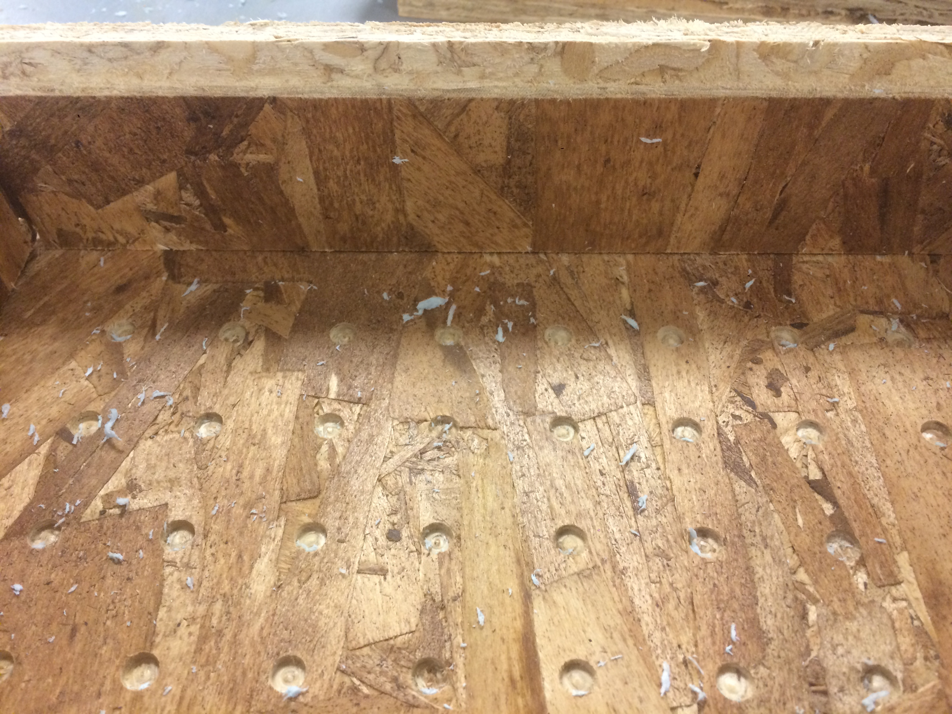
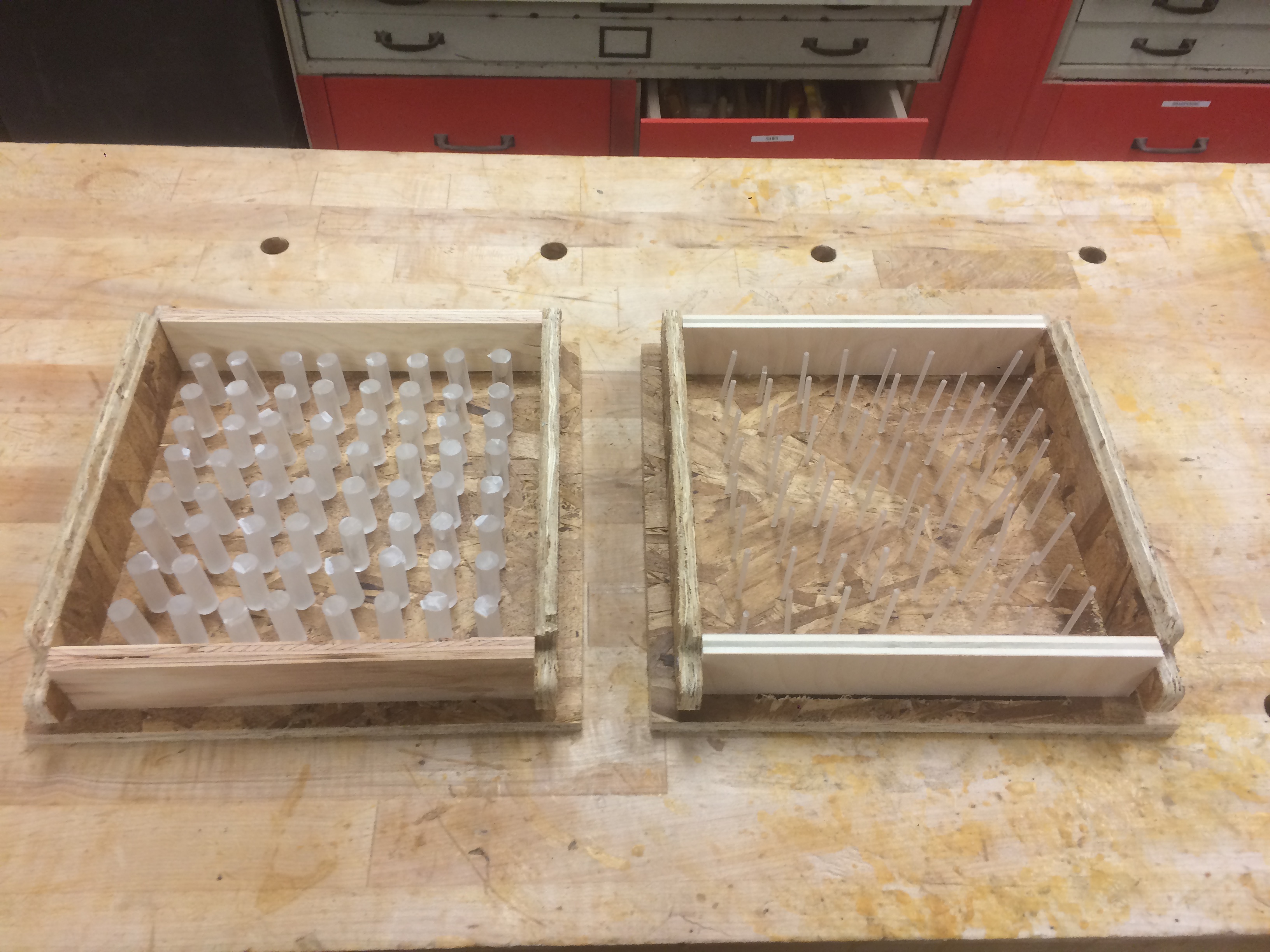
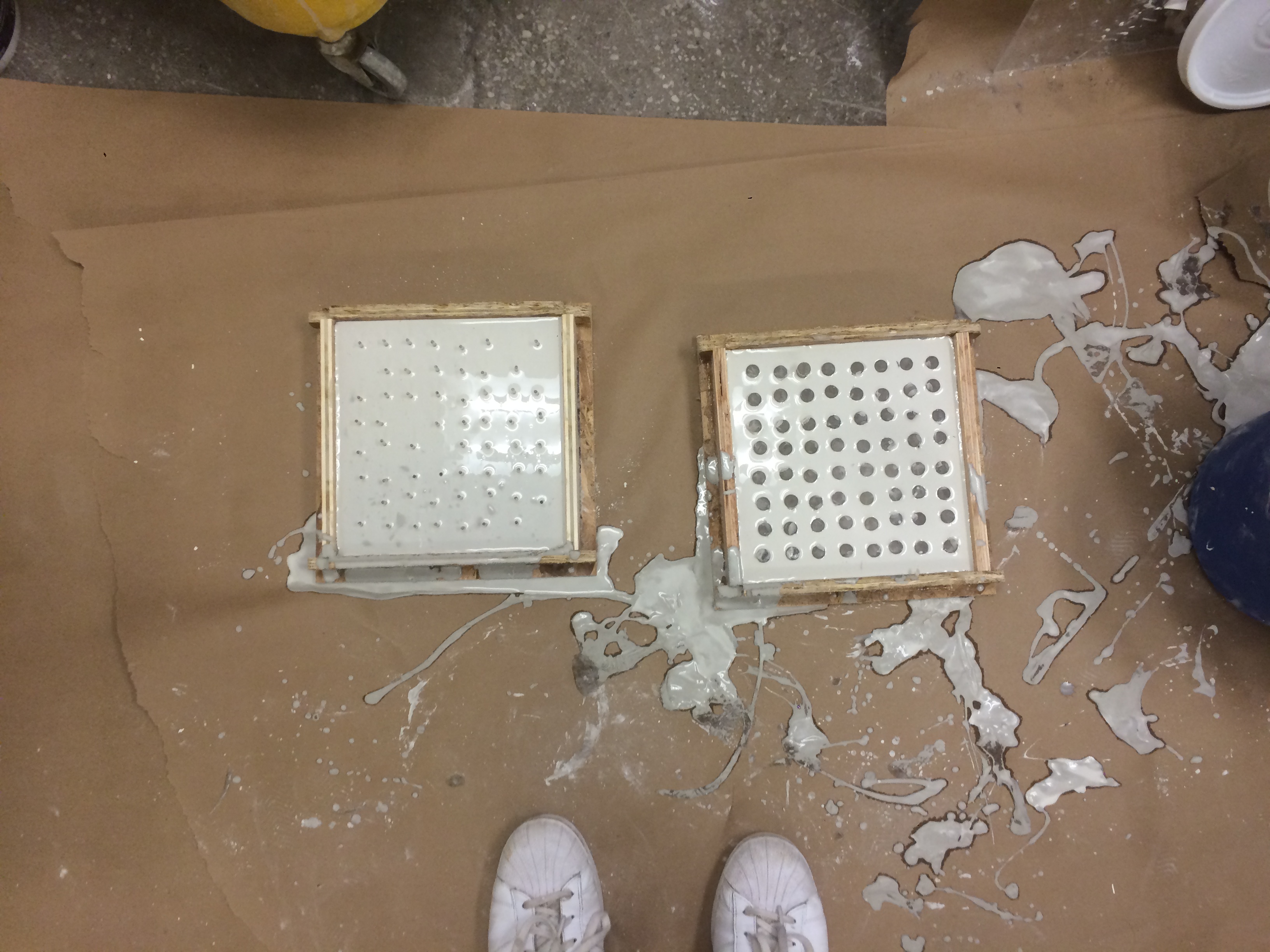
The pressfit worked really well in some places like above, however, due to the low strength of the wood a lot of the tabs cracked and a few places left pretty big gaps that I did not trust casting into so I cut a few smaller pieces on the band saw and made the molds.
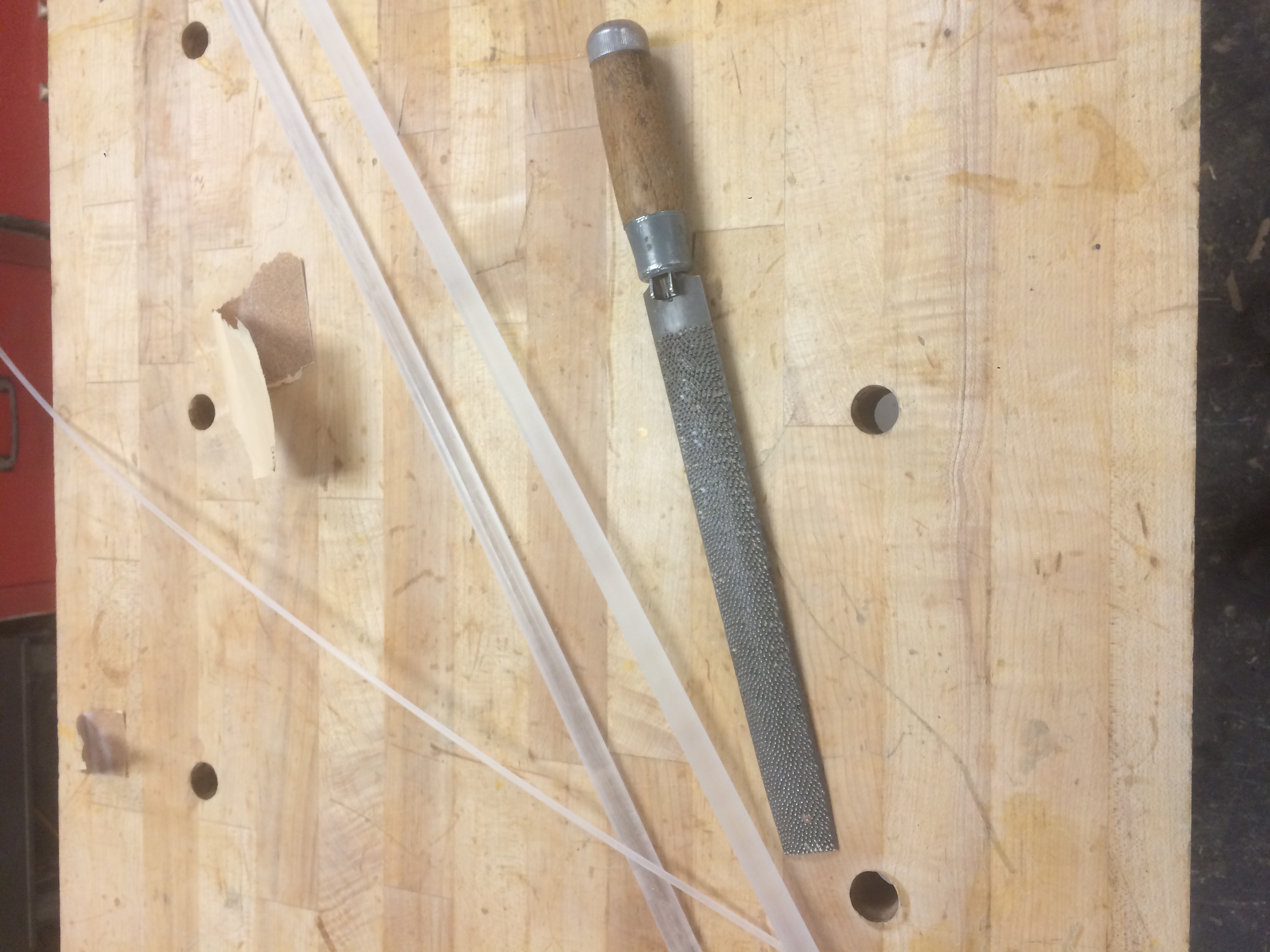
I had to score and sand the acrylic rods to make sure when I cast them they wouldnt slide out of the concrete. A small but very important step.
DO WEAR A MASK DURING THIS PROCESS
Sanding acrylic produces a ton of very fine particles that travel very easily and can enter your lungs. However, after I finished this I simply pushed the acrylic rods into place and the molds were ready for casting.
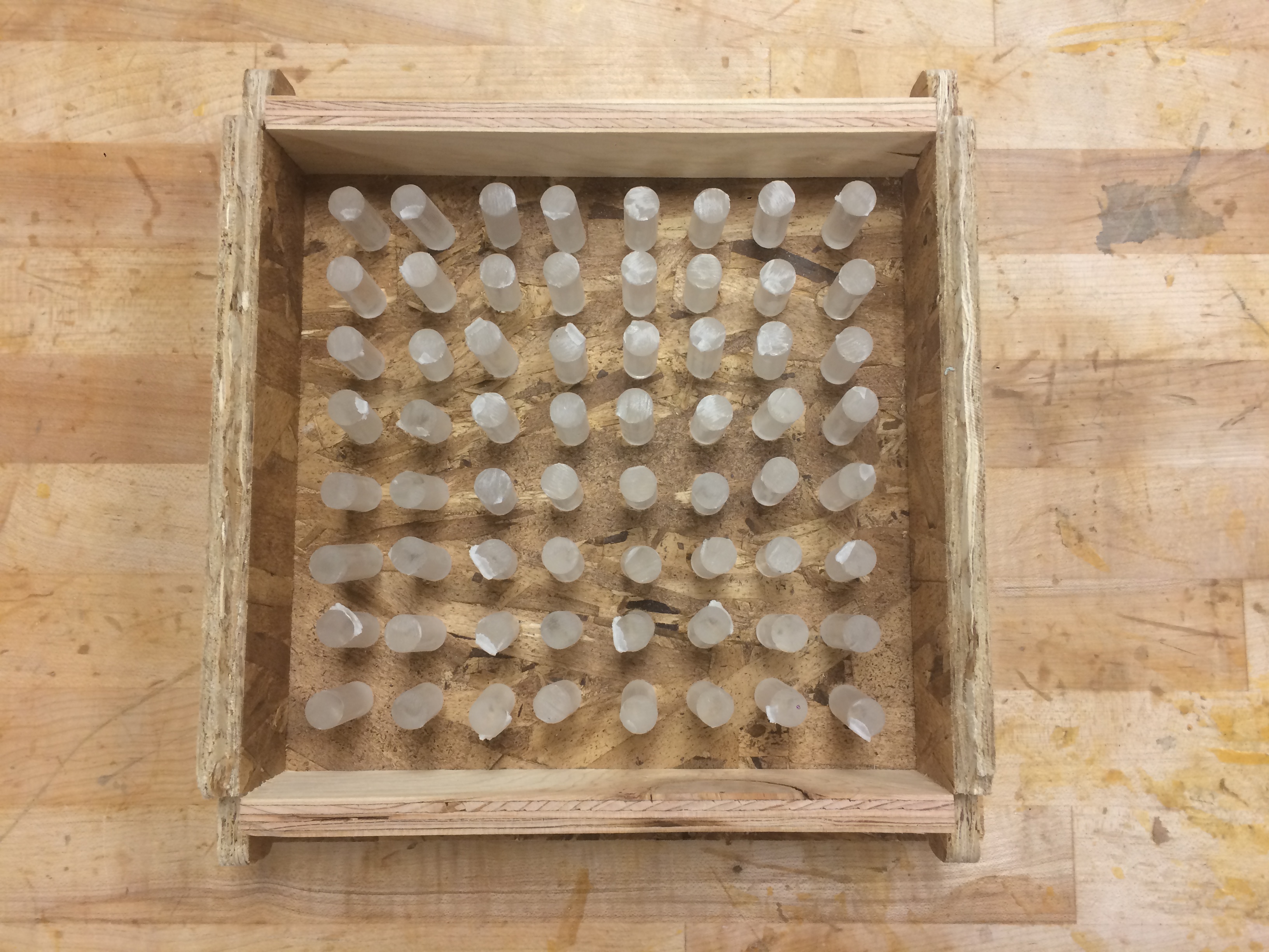
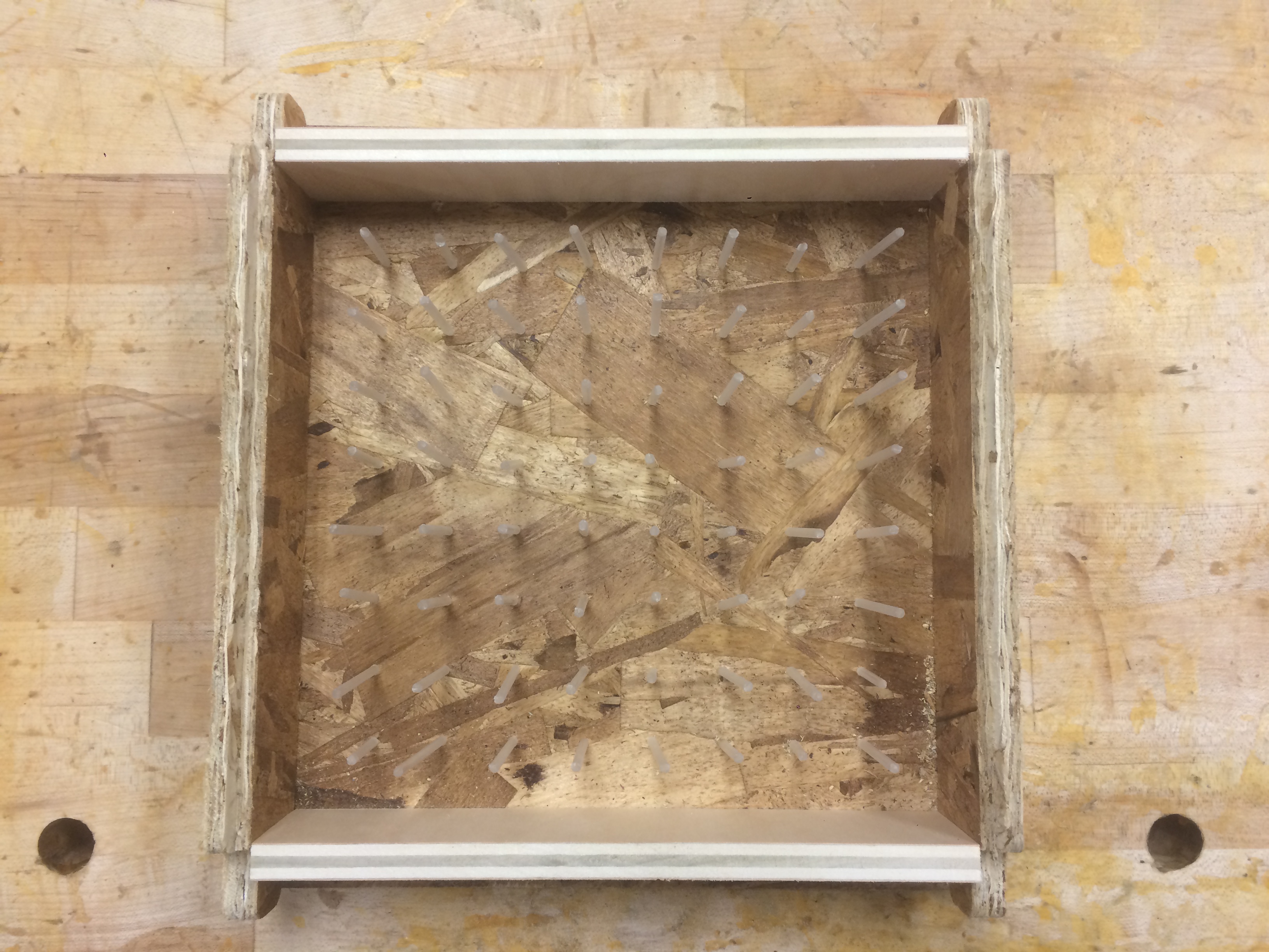
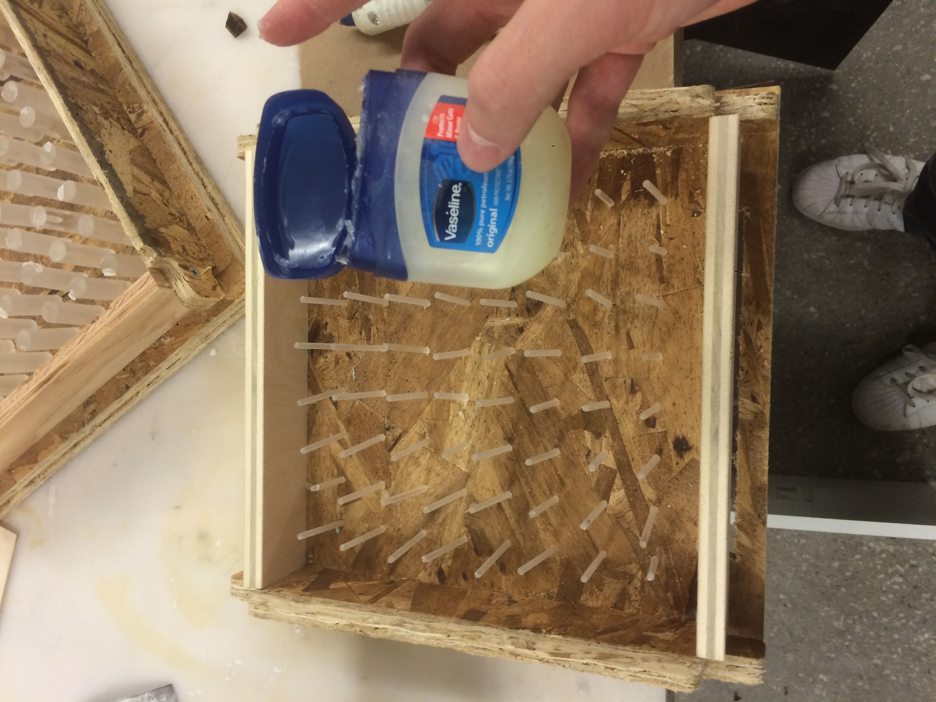
Mold release is an extremely important step as well so make sure to vaseline the molds up so they can be removed after the process.
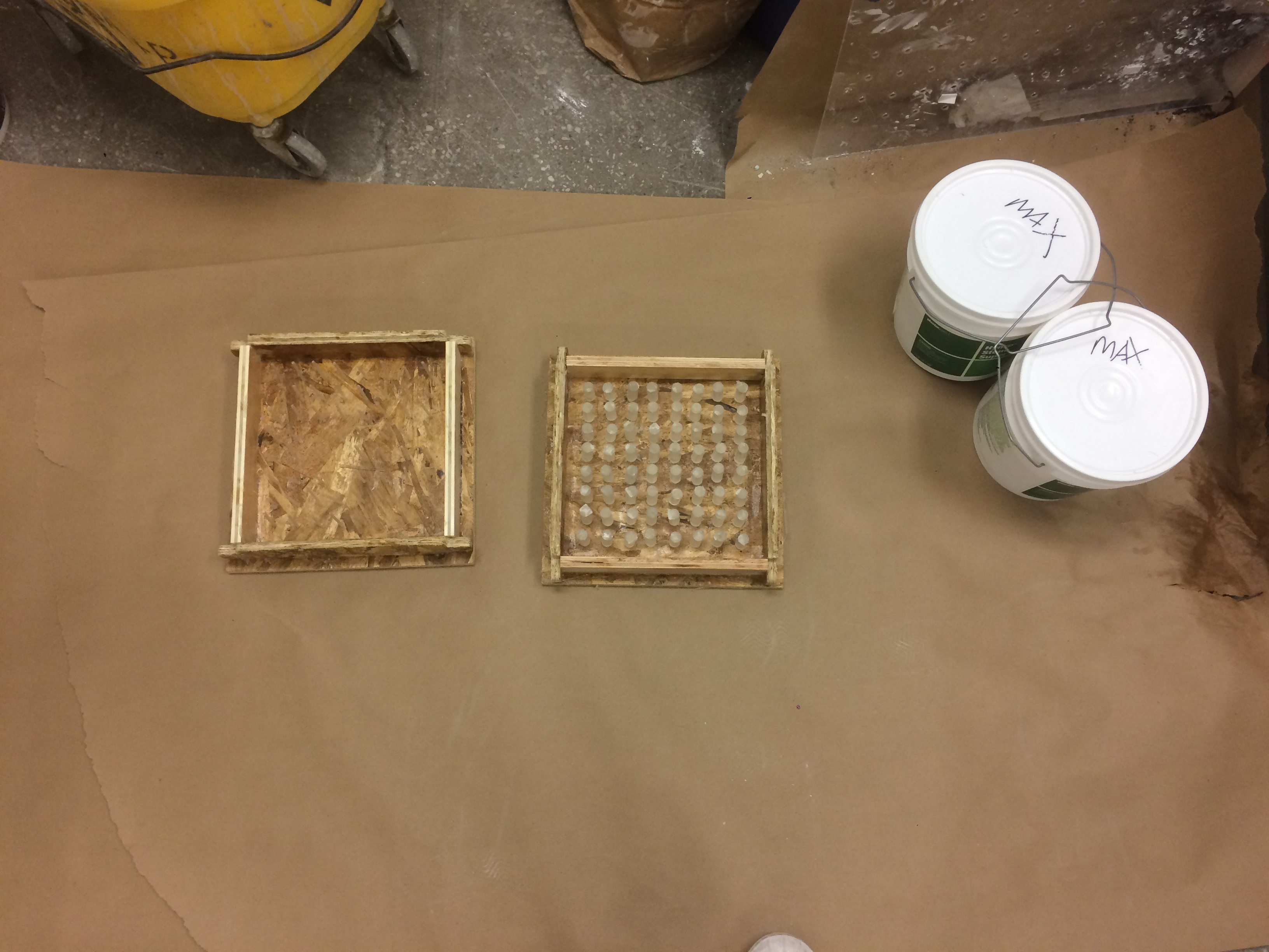
Next up is casting. I am using a hydrstone. A quick datasheet google reveals the balance is 22 parts hydrostone to 100 parts water in weight. I prepare myself a little zone and put down some paper not to make a mess and begin to mix.
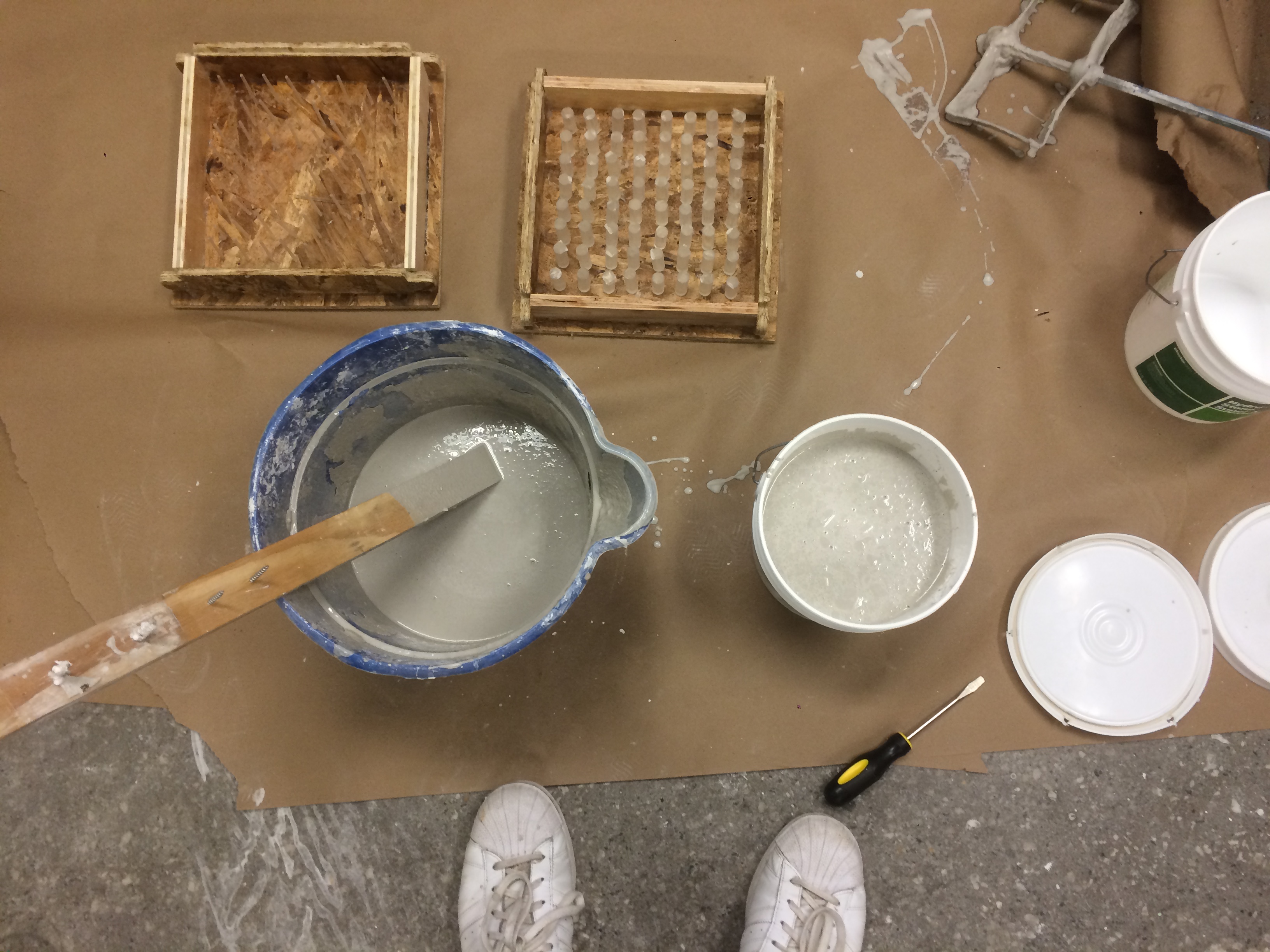
It got a little messy due to a small issue I had with a funnel getting clogged but other than that, casting it went smoothly. Ideally you do not want to cast leaving such a large surface area exposed however due to the trouble I was having aligning both sides of the mold to the acrylic rod I just decided to cast from the top. In the future I would not do this again as it effects the curing.

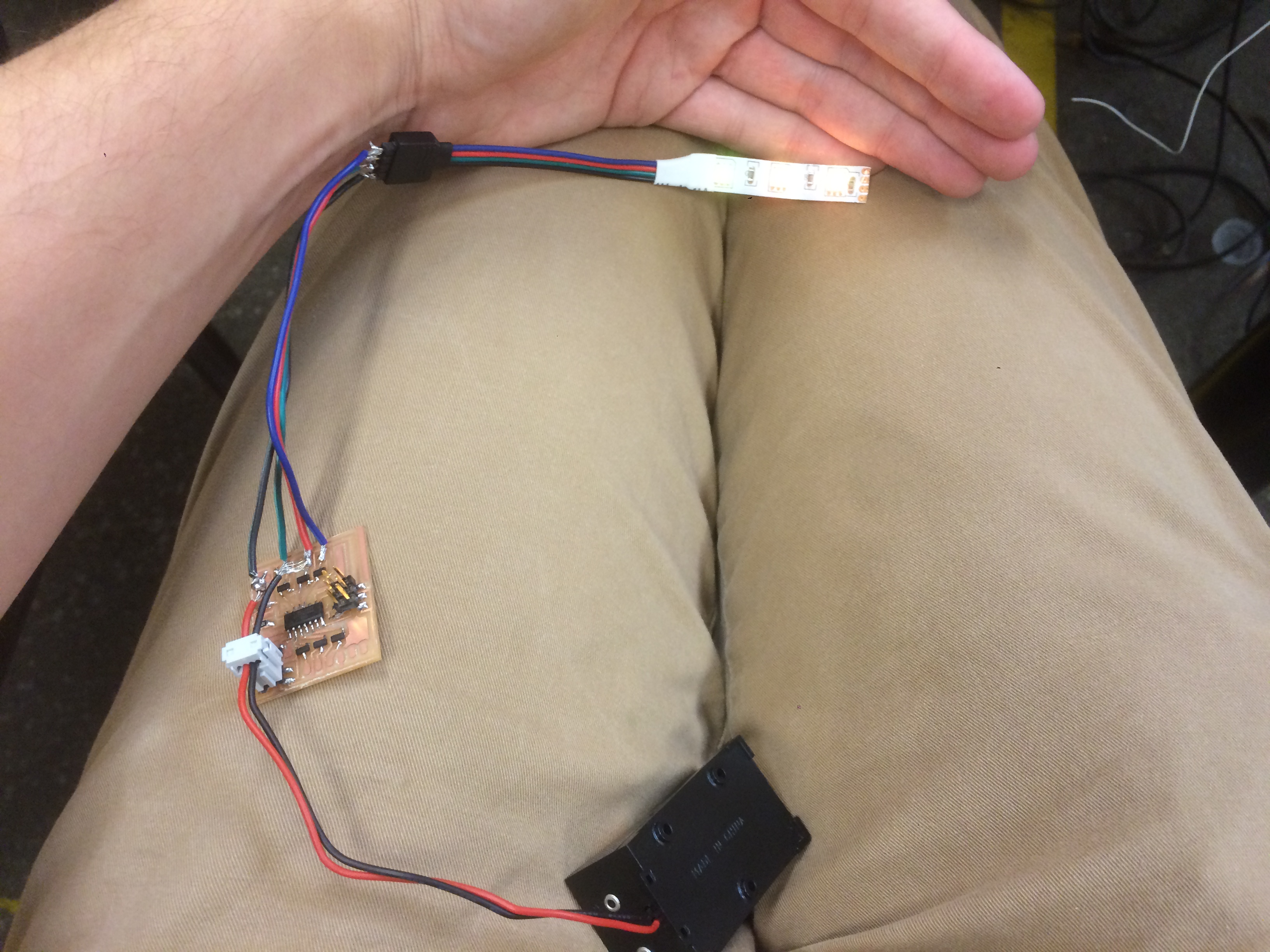
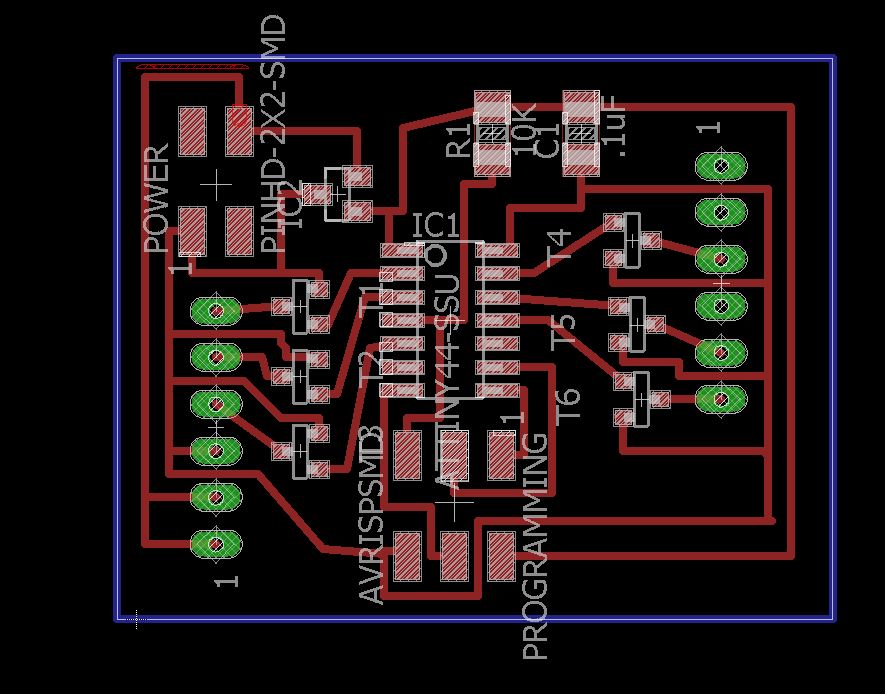
While I was waiting for the hyrdostone to cure, I started milling the electronics. My boards are available here:
Board: FINALLED
Schematic:
FINALLED
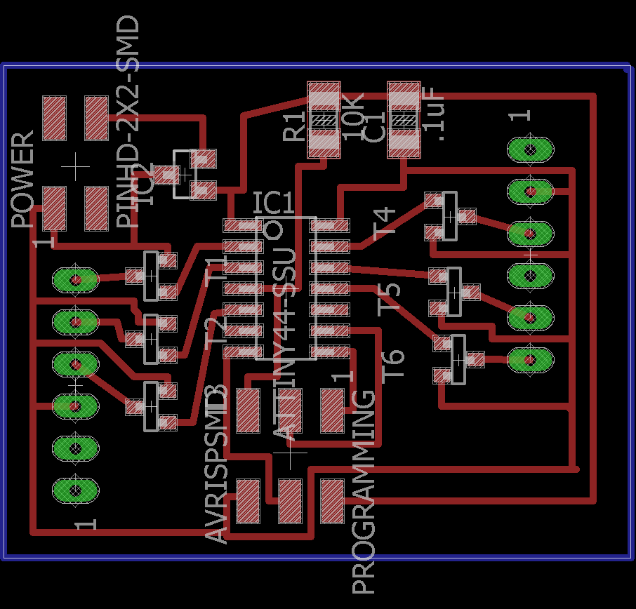
The board is powered by 9v battery, the minimum for the LED strips I have. Power comes into a regulator that drops it down before going to the ATTINY 44. I then have 6 N -Mos fets that control the leds so they are connected to pins on the ATTINY 44, ground, and pads that I will solder wires to and from the LEDS.
N- Mosfets work like a hallway (as described by Nadya) essentially the voltage is always going to the led but the mosfet is a gate that the chip can control and tell it when to open and close to let the voltage through, which it can do much faster than telling the led to turn on and off.
At this point milling and stuffing these boards is like shaving, mostly easy but sometimes you screw up.

The board came out and now I just have to stuff it and attached some leds.
Update
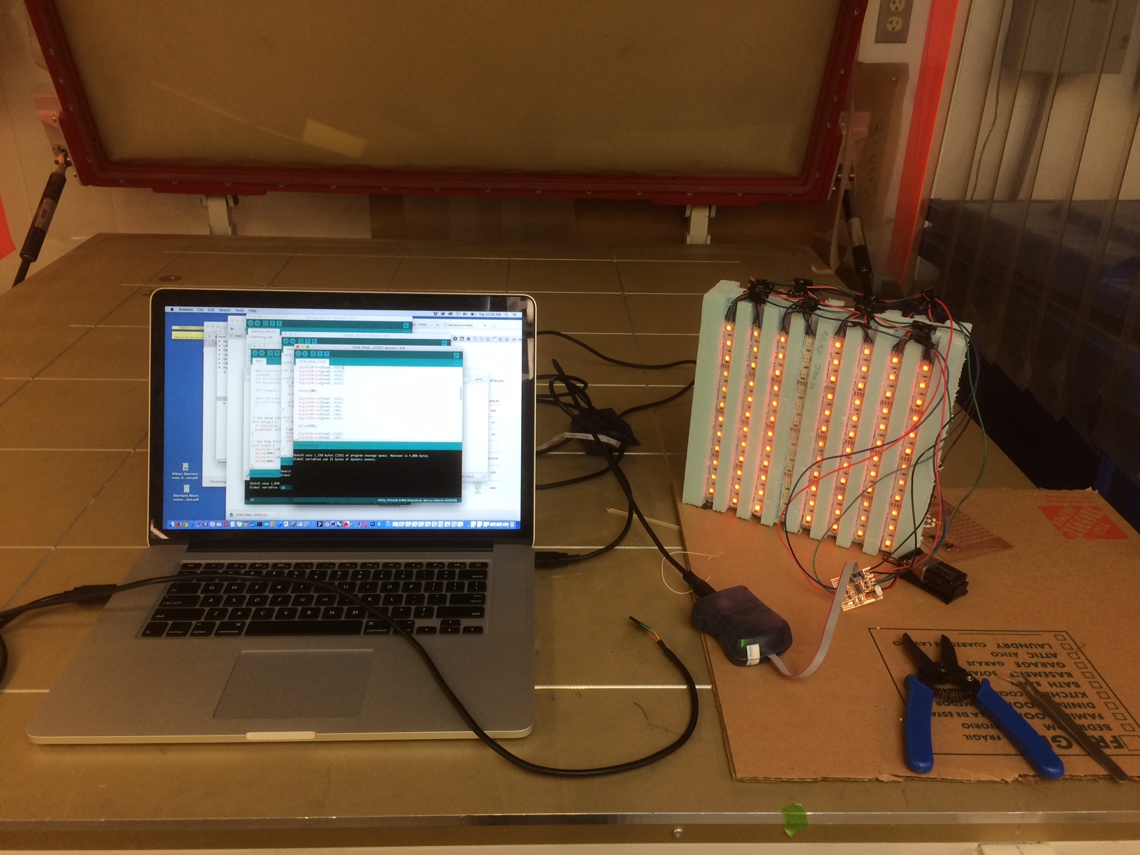
Today, I attempted to solder on the LED's and test the programming. The first step was to program through arduino with the AVR ISP:
For tips on setting up the library go to: http://highlowtech.org/?p=1695
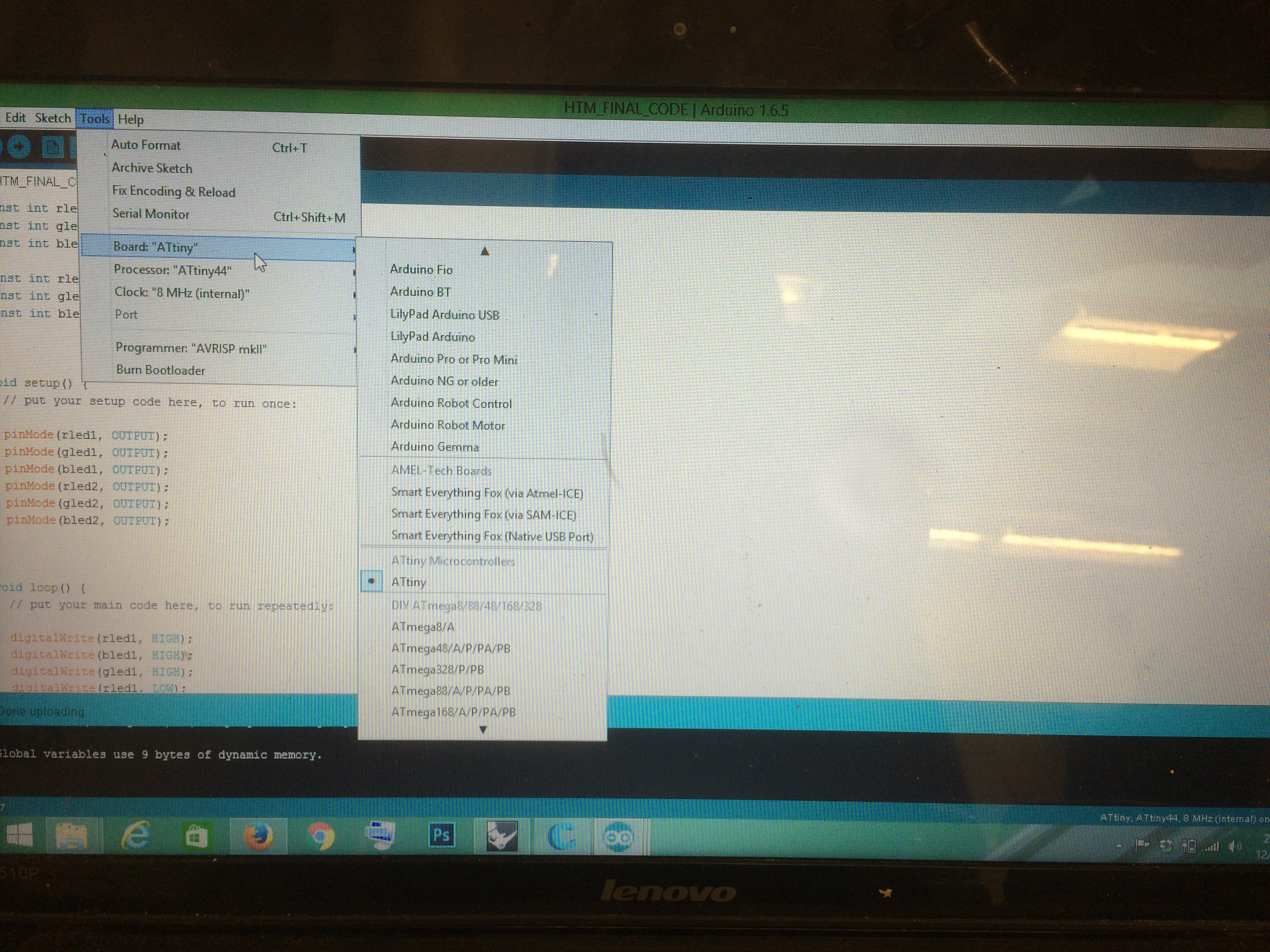
This explains the very simple and easy process of installing the ATTINY libraries to arduino for you to upload. The process went relatively smoothly and it was time to test if the lights and board actually worked. My code can be found here:
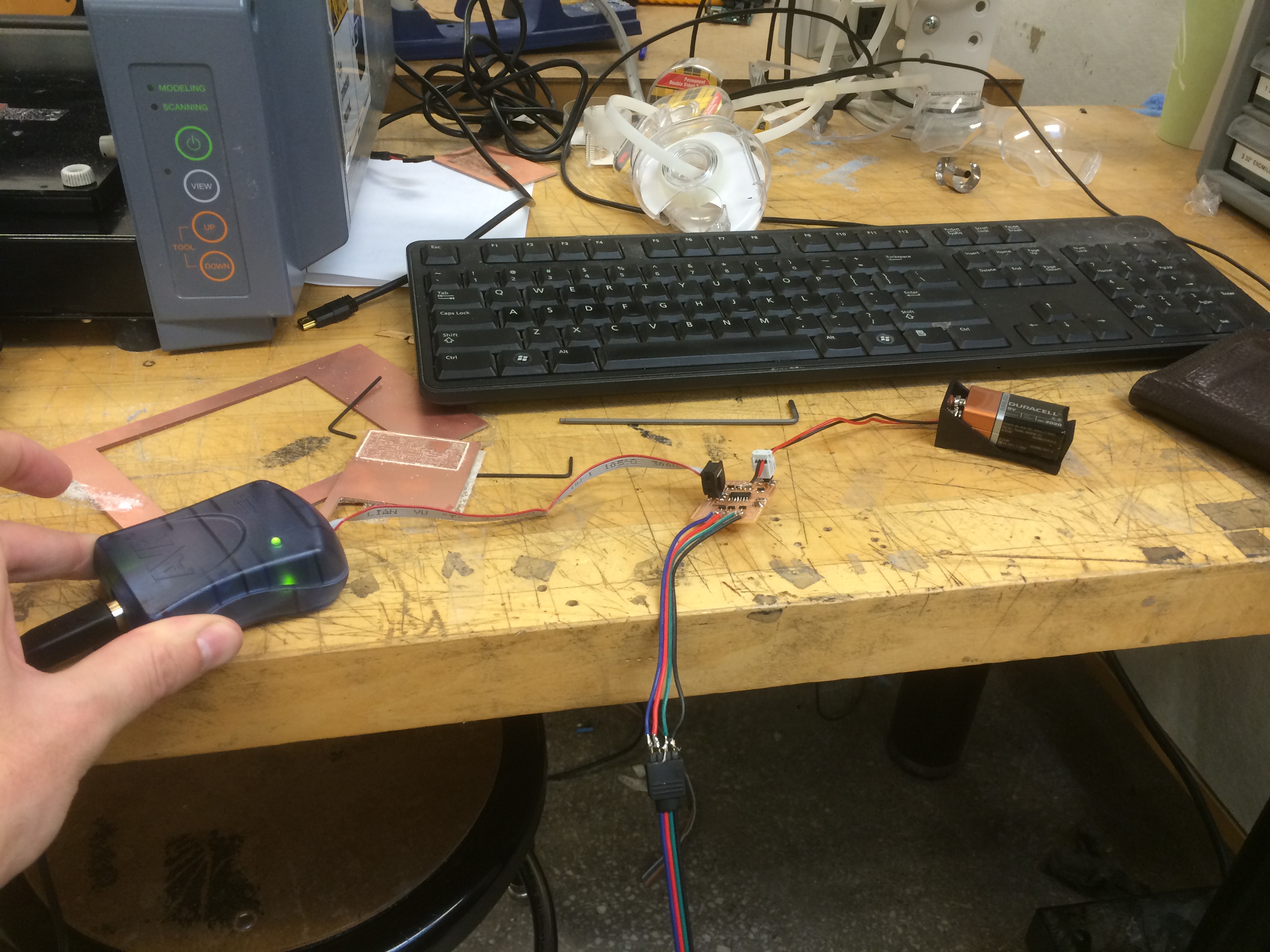
The program uploaded but no lights. After looking back at the LED data sheets, it seemed like it might be calling for voltage instead of ground, so in an attempt to just test if that was the problem, I desoldered the black pin from ground and soldered it directly to voltage from the battery and the lights started working and fading as they should from the code.

After doing this, I decided to make a new board, it would be very simple and quick because I have extra pins in the board design, I just routed two boards from the voltage in to the pads. The revised board looks like:
Also my board layouts can be found here:
FINALLED (brd)
FINALLED (sch)
After remaking the board, I soldered all of the LED's for the project to get it out of the way, and here is the result.

At this point I am a little nervous...
I programmed it in arduino and everything is working minus one strand that must have gotten bumped in transportation.
If I plug it in and it works, if it doesn't I am going to be a little stuck and have to go back to the drawing board. I decided it would be fun to have Liz record, and in the recording you can see my jaw drop a little bit when I see the lights working. The video is available here:
The lights work, (in the video they are off on one side but that is because of the code. So I assemble all of the pieces together, and you can see both sides. 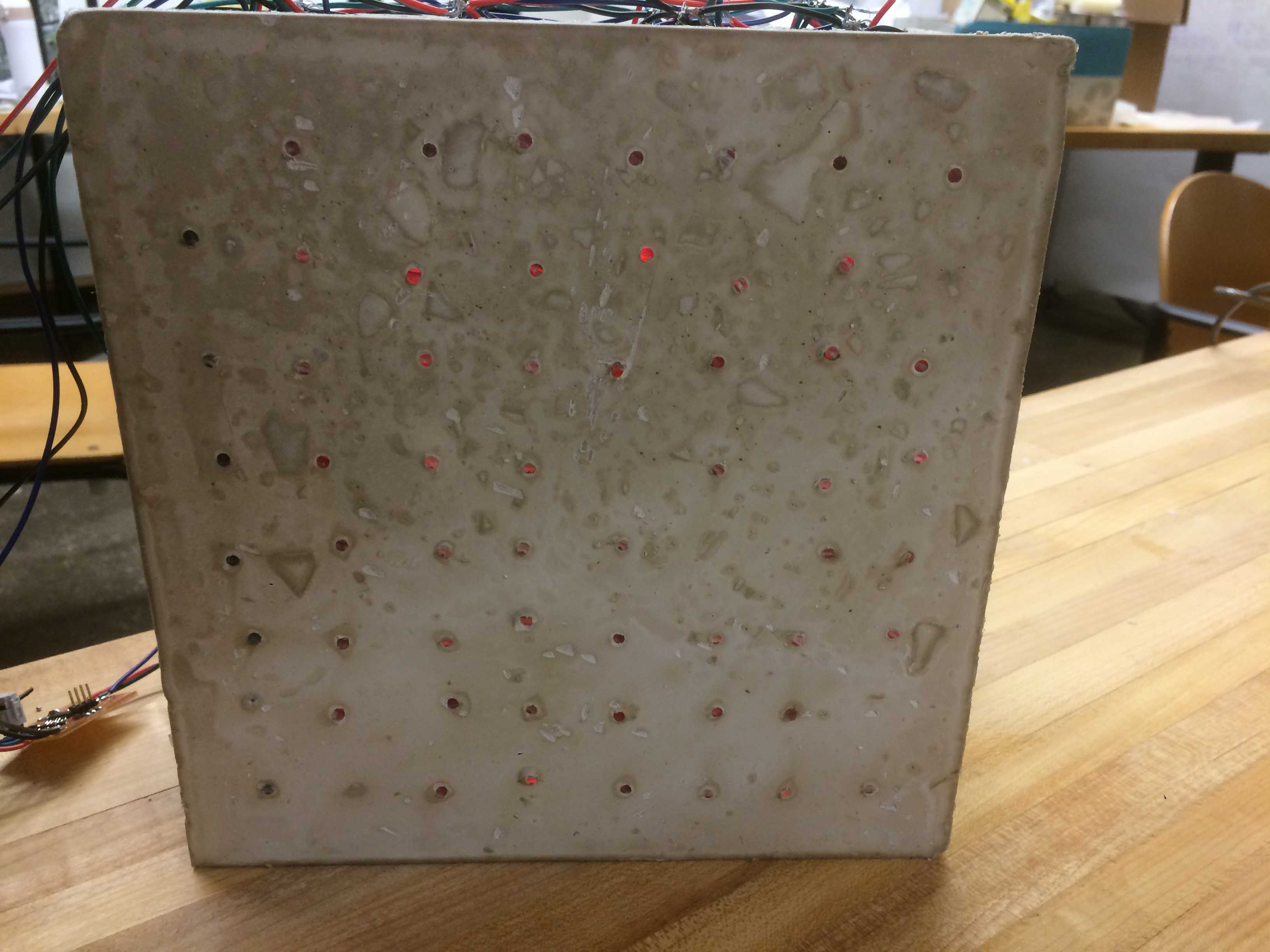
At this point I must have bumped one of the solders because of one the strips started working. This should be a small fix that I can do in the morning and will resolder and cover all of them in masking tape to secure and protect the connections. 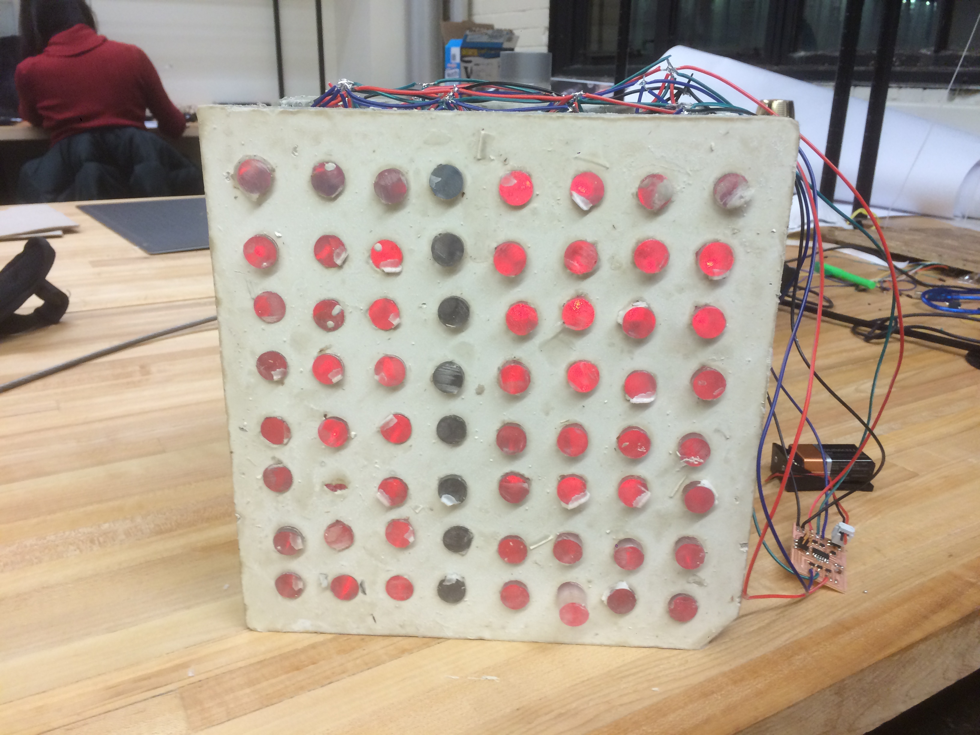
The faces also need a little bit of processing and touch up but again, I will finish this in the morning. Project (almost) complete.
FIN