For this week, I wanted to build a wifi controlled outlet. i.e.
somebody could go to a certain webpage and use it to turn on and off and outlet. I want to give a huge shoutout to Dan, who was super duper helpful in getting the project done. Once again, I can not stress how thankful for how helpful he was.
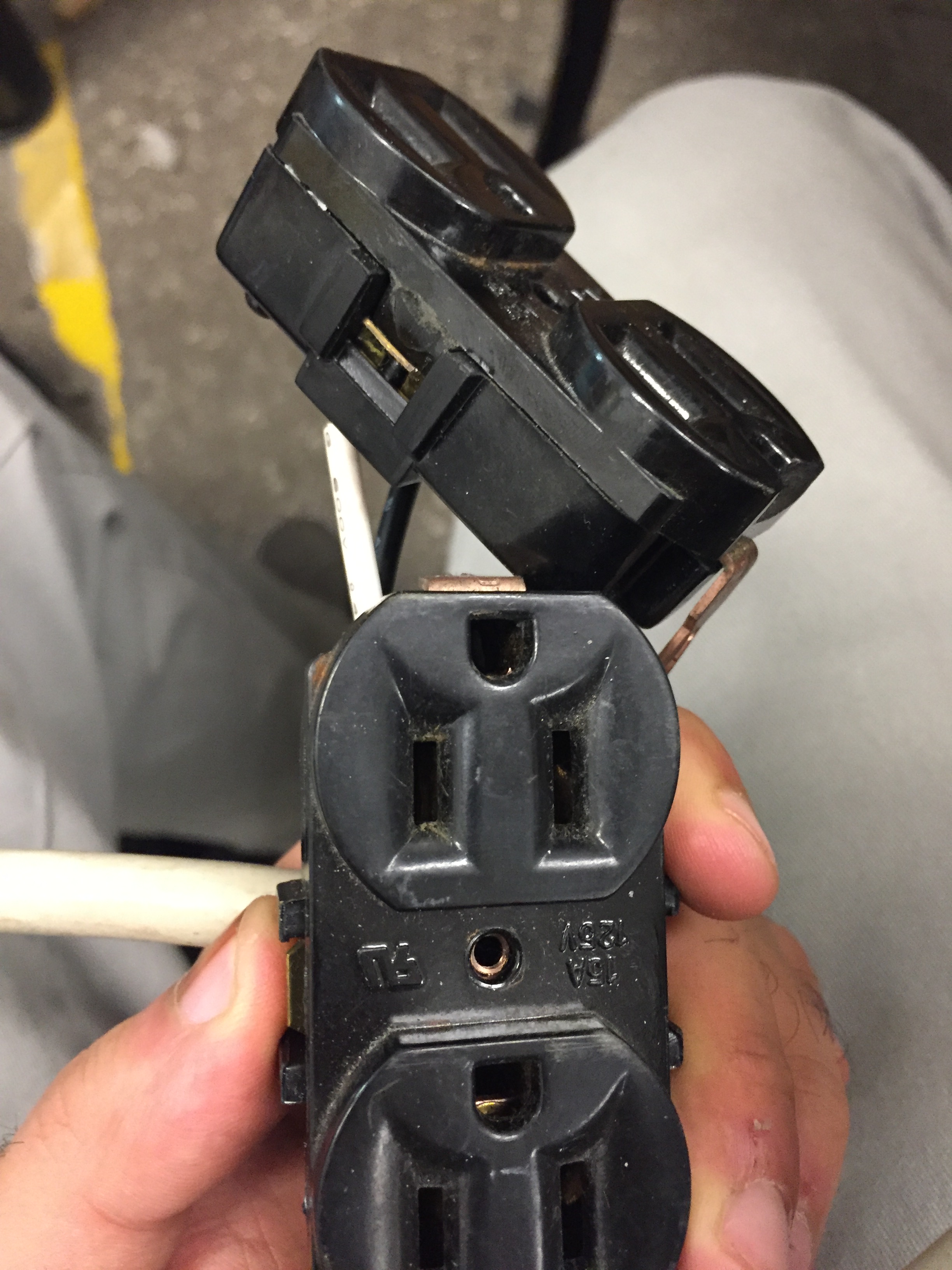
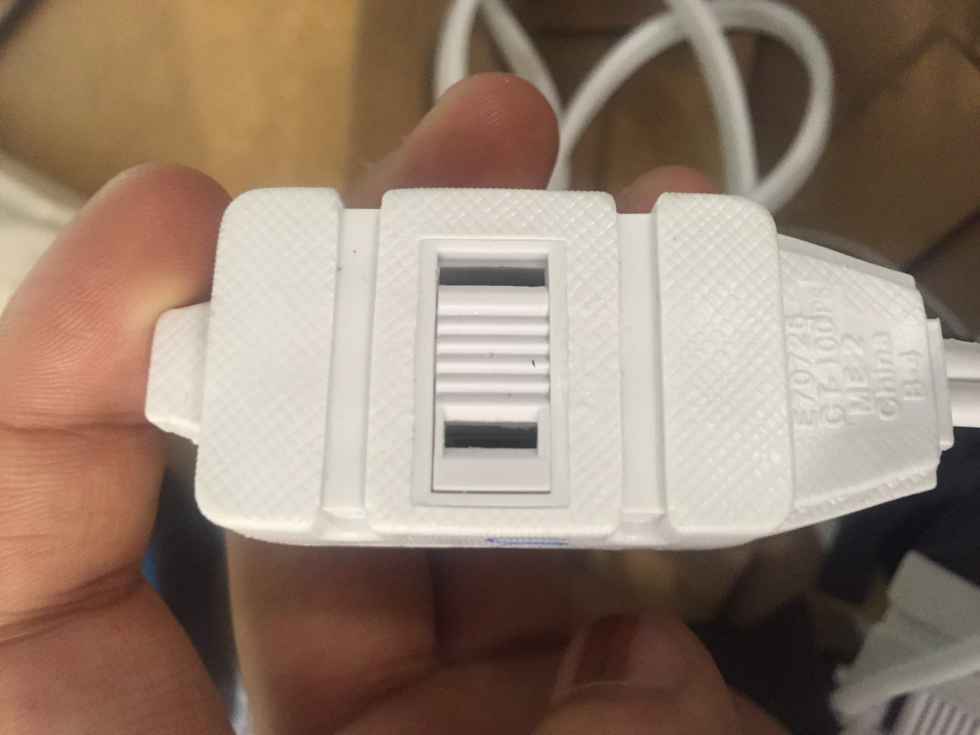
The first thing I did was break open a current outlet and see what was inside. The following pictures depict what is going on that webpage.
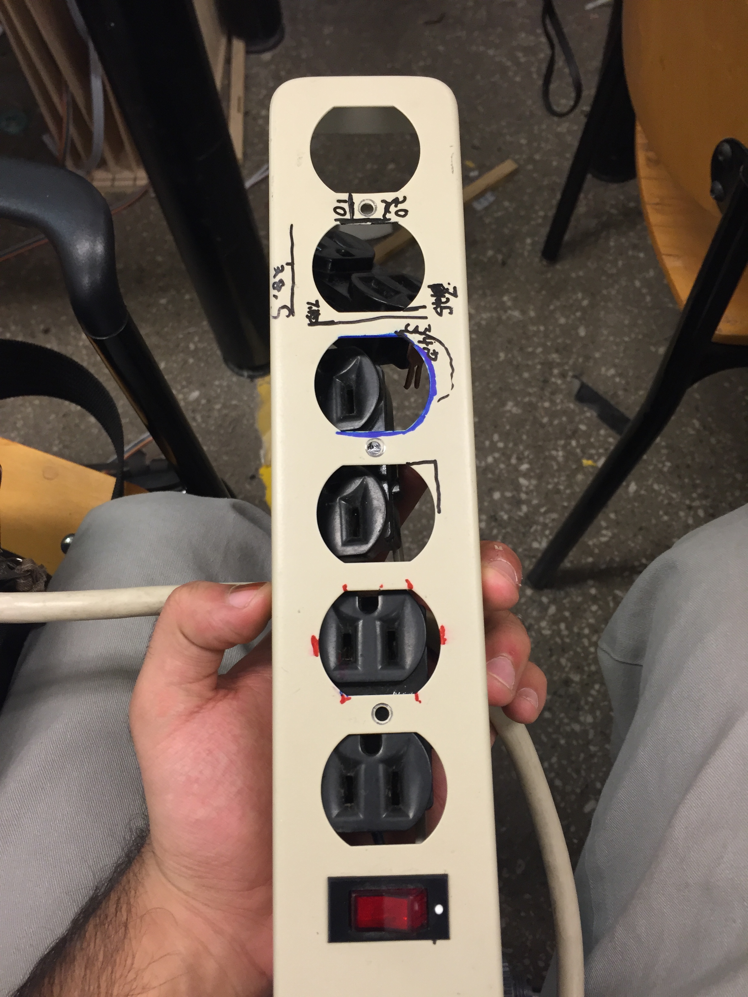
From my dissections of the interals of the outlets, I discovered that I probably needed to buythe outlets. They all are in parallel. They all get vcc and ground feeded to them. I was thinking of using a relay to basically switch off the flow of vcc to each of them. I would controll the relay using a micontroller.The relay was not in the inventory, so I measured it and made a custom one. Here are some pictures of this:
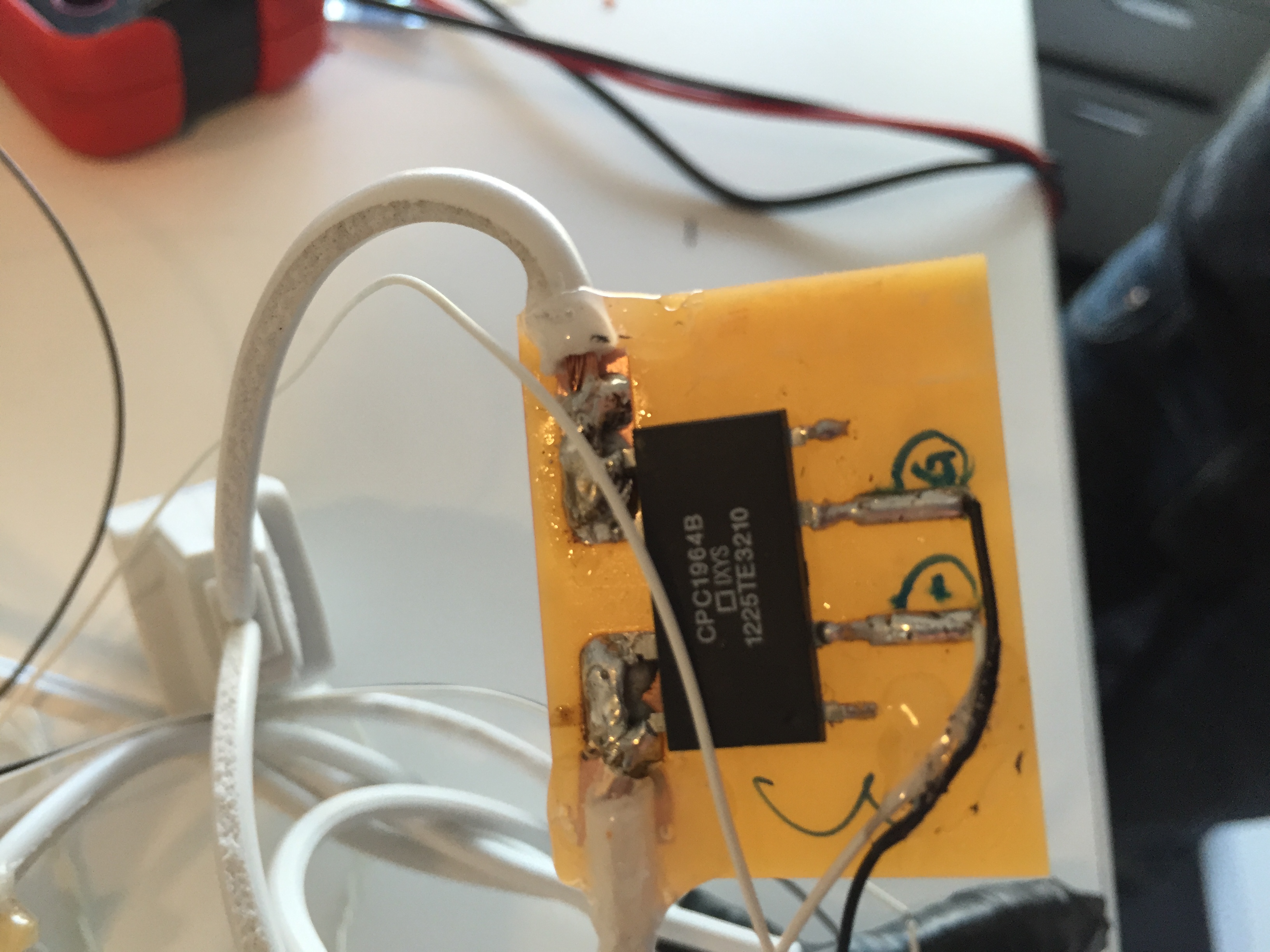
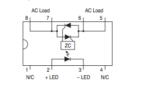
Also, the datasheet for this controller was really confusing.Only through some trial and error were we able to figure out how in the relay works. Just in case anyone else wants to ues it again, the nc pins nothing and are just there for contact. The led + and led - are voltage pins which we use to drive it on and off. AC pins 8 and 7 are respectively connected
and ac load pins 6 and 5 pins are respecitvely connected. When high voltage is applied to the voltage, the whole switch is turned on.
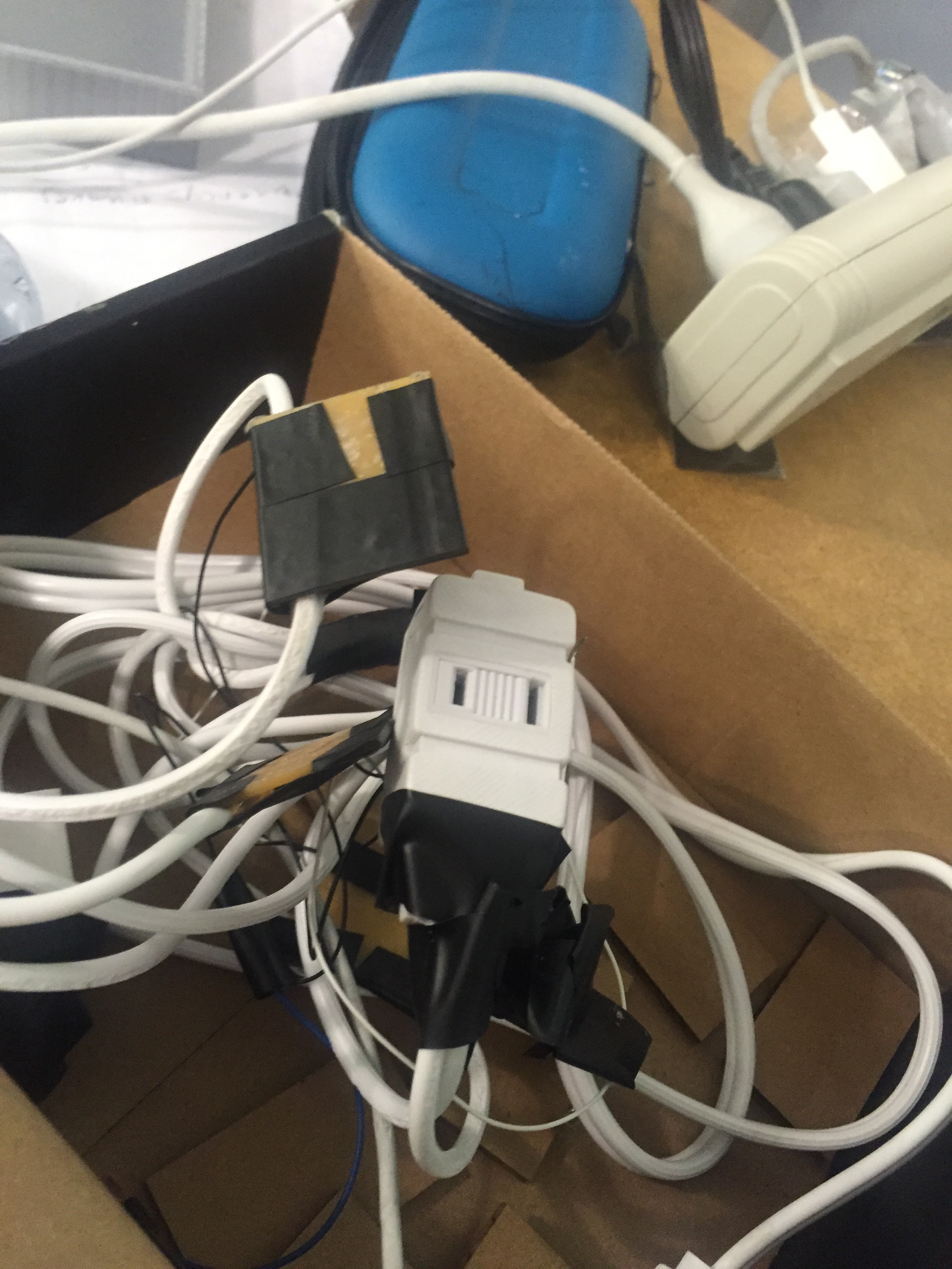
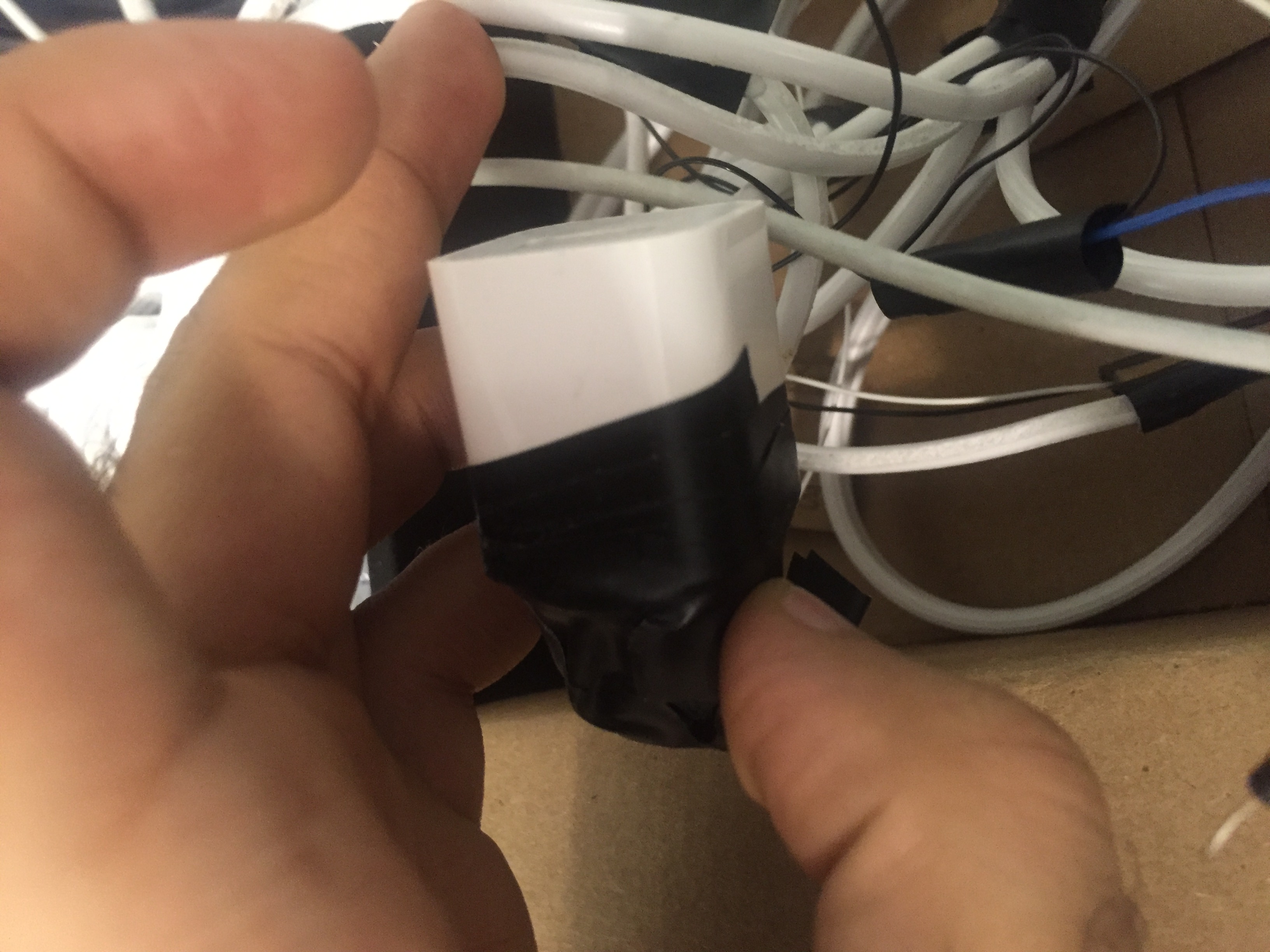
The next thing was to actually assemble all the components together. We basically stripped open the wires from the outlets that were already bought
and basically soddered them and routed them accordinly, i.e. feeding ground to all the outlets, but the vcc to the relays, and then feeding the relays to the outlets.
Here are some pictures of this happening. Heavy, use of electrical tape was needed.
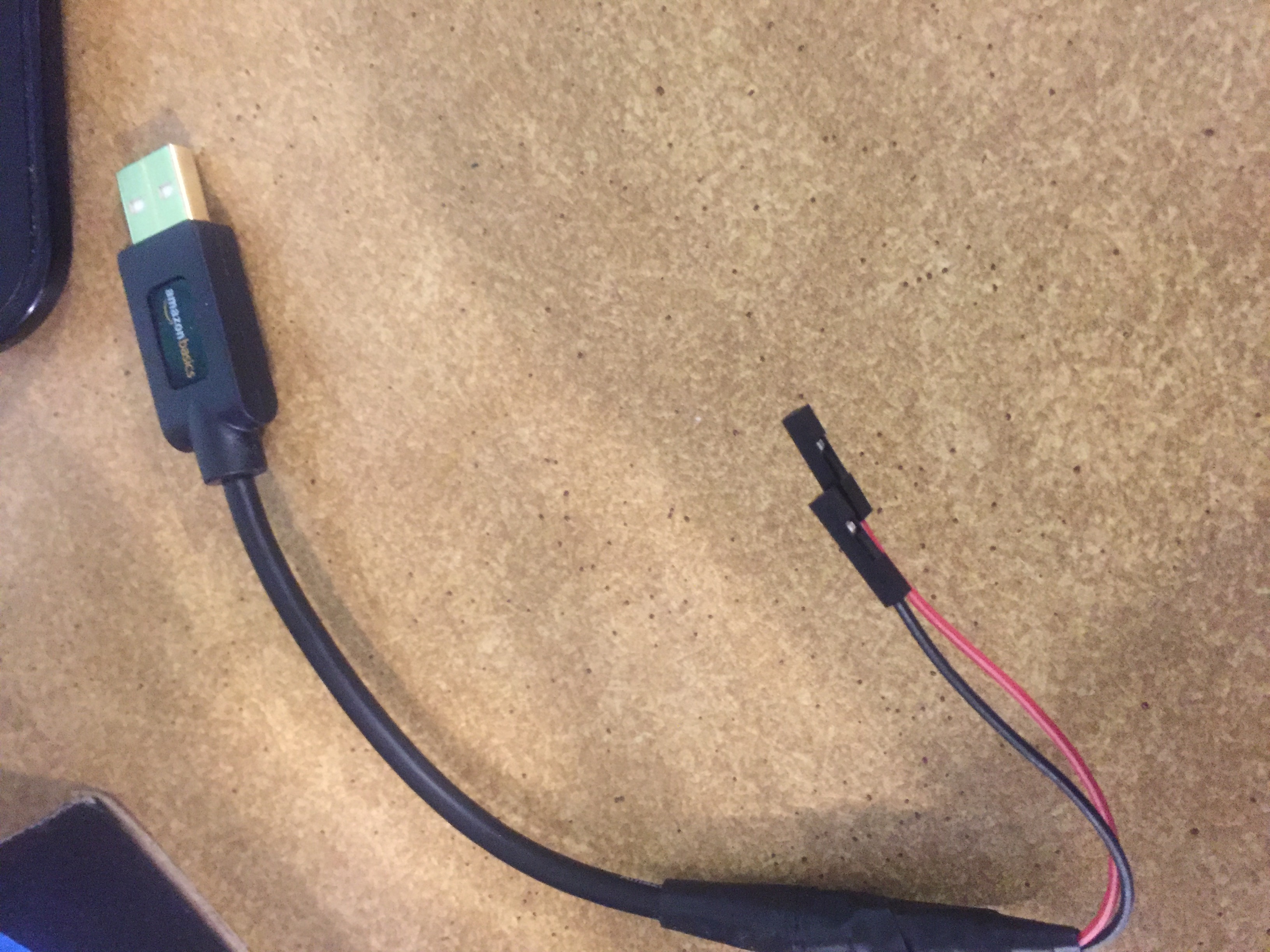
One problem with this is we needed a way to power the microcontroller. The micronctroller is used to taking in dc current at a much smaller voltage, then
what the outlet provided. Therefore, we hacked a iphone jack and used it for our design, basically as an ac to dc converter at the required voltage.
Here are some pictures of that working. We then too a usb cable and hacked that, so we could get a short calbe that could power our device.
After this, it was time to test everything out. The following video shows that everything is working. We have a iphone charger, a light, andother charger
that lights up green. Every two second something turns on, then there is a two second delay and then something else turns on. The video of this working is shown here.
Now, that we had the basic pieces working, we needed to house a case for this. I originally wanted to make a fancy case,
but I decided to make a simple case. I think laser cutting acrylic might have been bogd, but I made up my mind too late
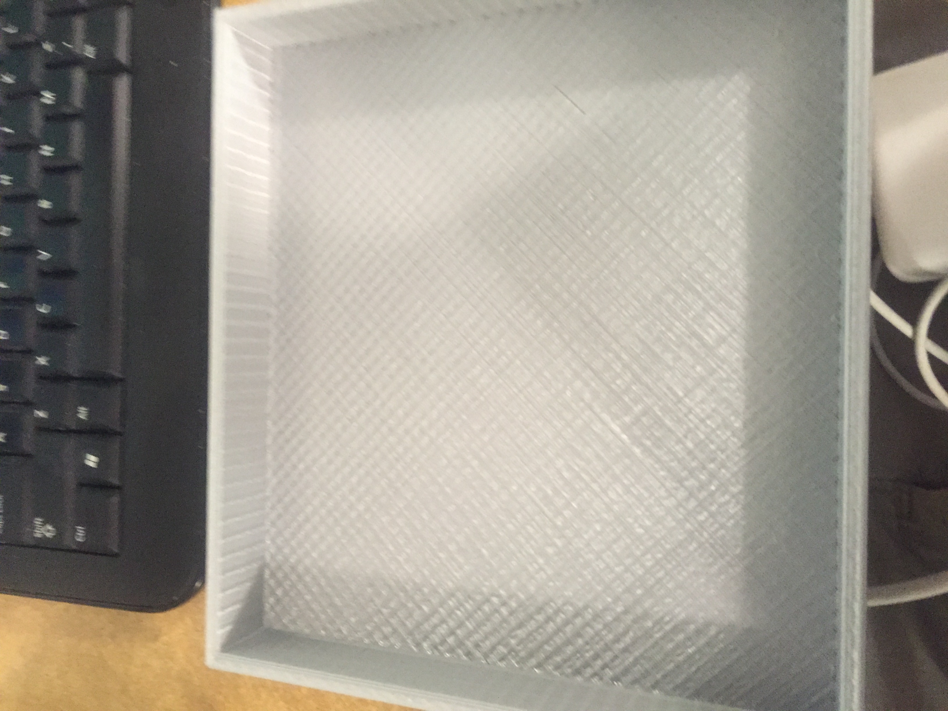
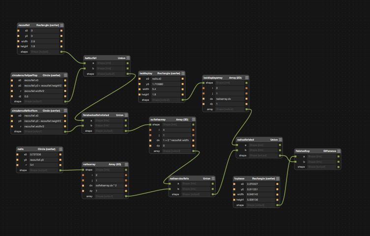
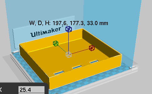
to change to a simple case, so I just went with the 3d print. Here is the picture of the antimony file of cases and some other
pictures. I made it as big as possible just so it would be easier to stuff.
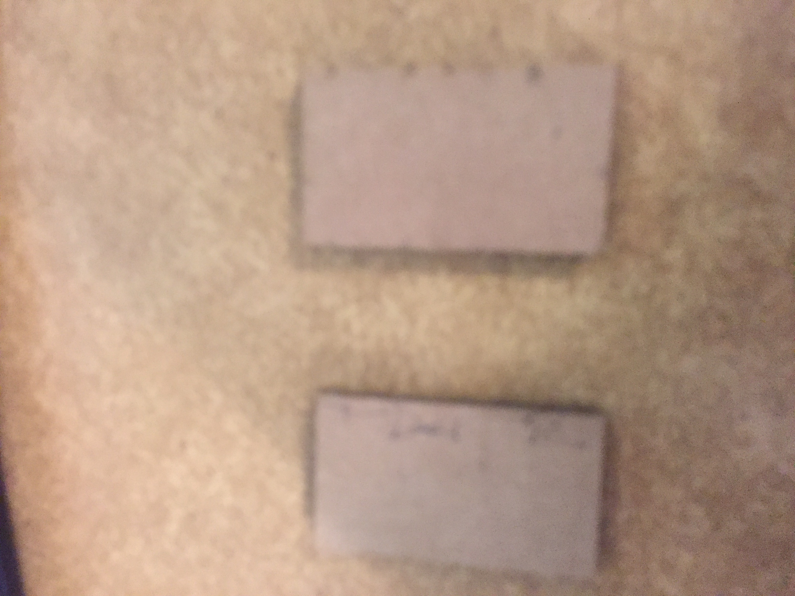
One problem I had, is i soon relized that the power outlet I was using were about the same height
as the iphone cube, so I had to put something to raise the heights of my outlet. I decided to use
cardboard. I lasercutted a bunch of cardboard pieces of the required dimensions as seen in the diagram below.
Finally, I needed to actually stuff the box. Here are some pictures of that happening.
I basically used a lot of hot glue and tape.
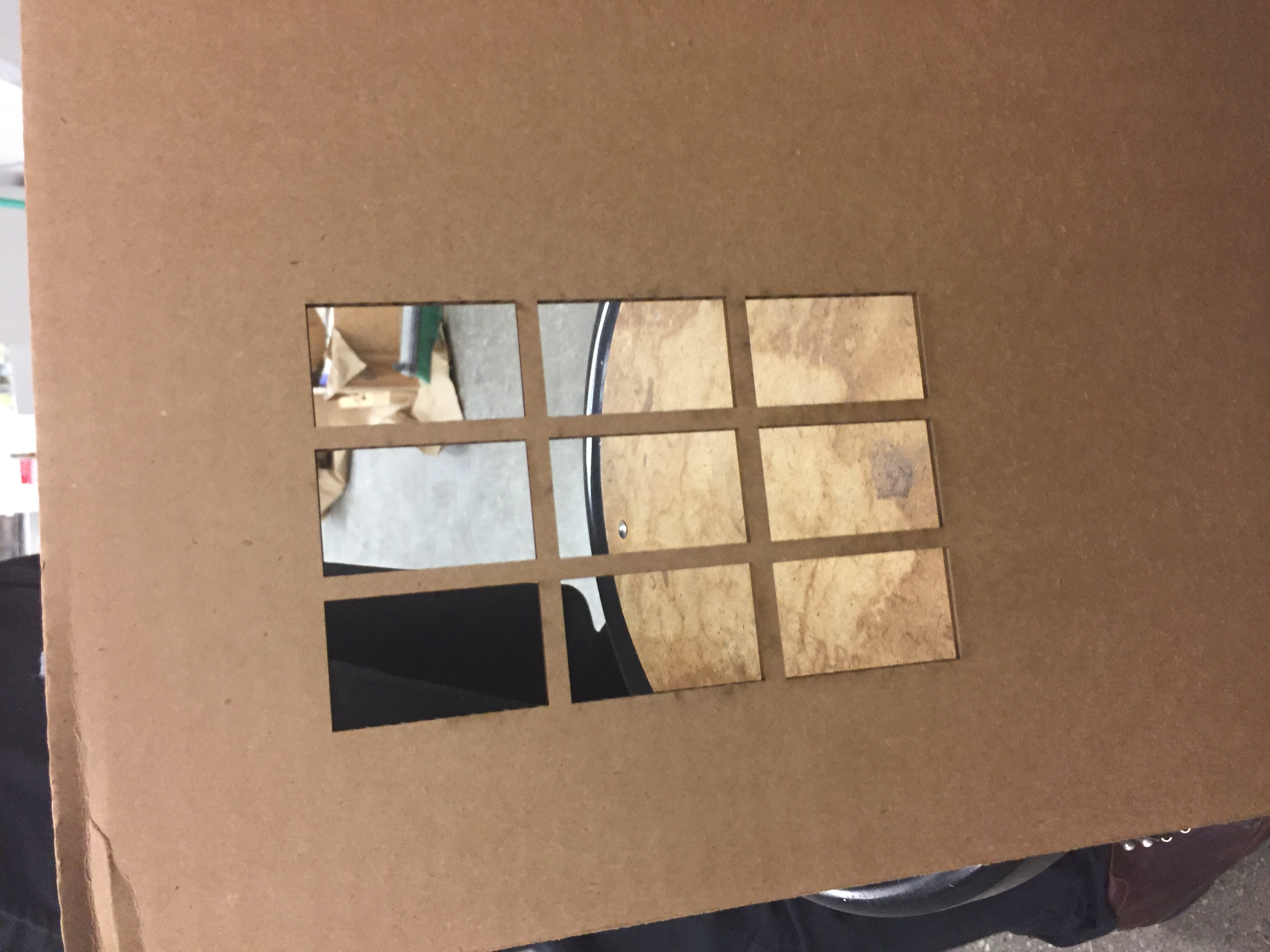
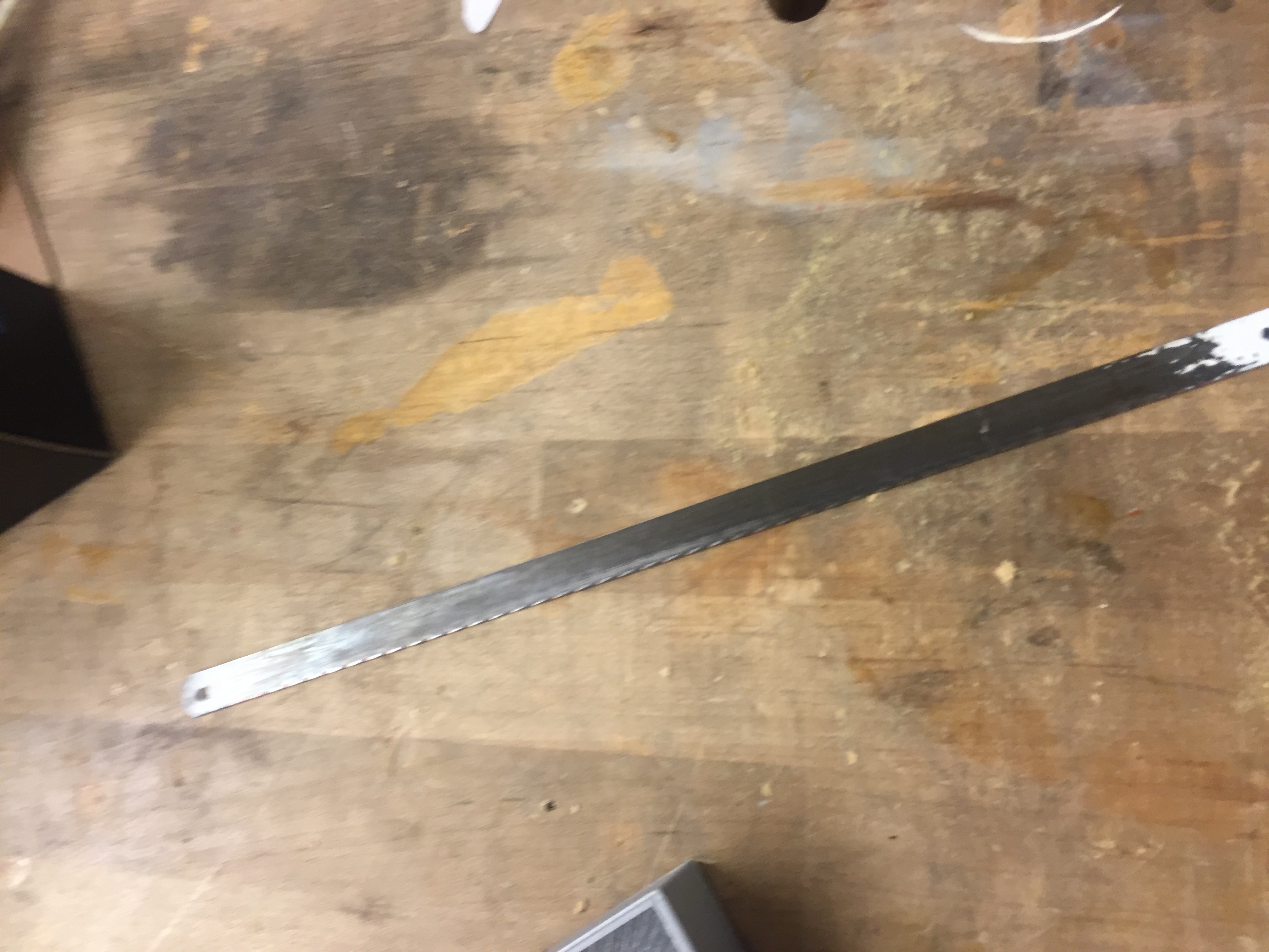
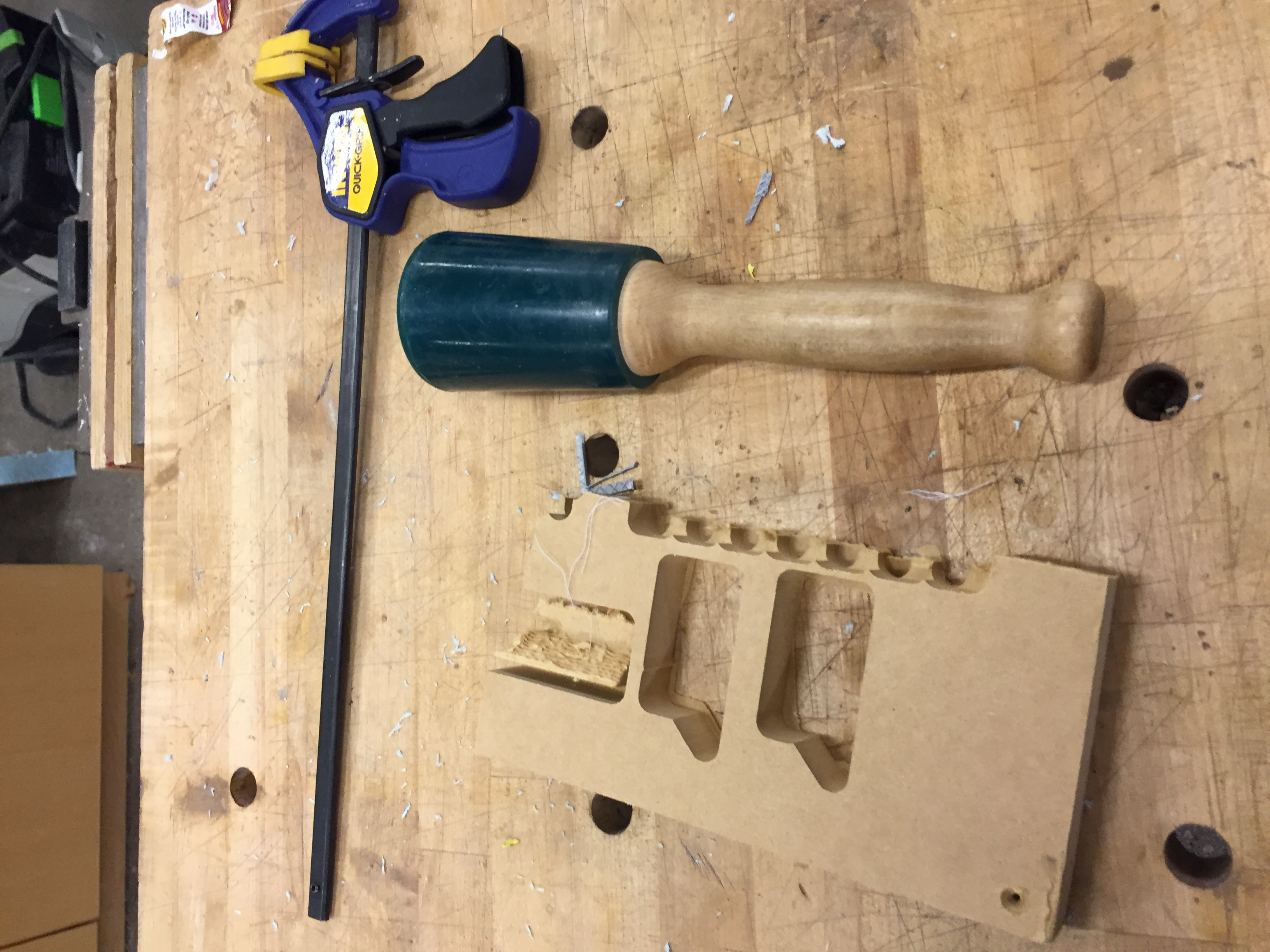
One problem that I was made that I forgot to include the wholes in the box when I made it
for the power cable to the wall to go through. I decided to draw that happening. Here is a picture of that happening.
I got help from the shop ta to use a chissel and also used a super small hand saw.
Now, that I had the case working, I decided to try my hand at the networking. It was a big problem that we didn't have networking week.
The ta's recommended I used the esp8266-12e, not the 3e that was in the inventory. I found one in the inventory, but it was from a different
manfacture and used a different node lua framework and not the attiny. I also tried using the real 3.3 regulator and not using a 3.3 regulator. Another problem was we didn't have the right 3.3 volt in the inventory. I tried
hacking around and trying to get it work, but it wouldn't and I went to office hours and they couldn't figure it out. The regular esp8266-12e is supposed
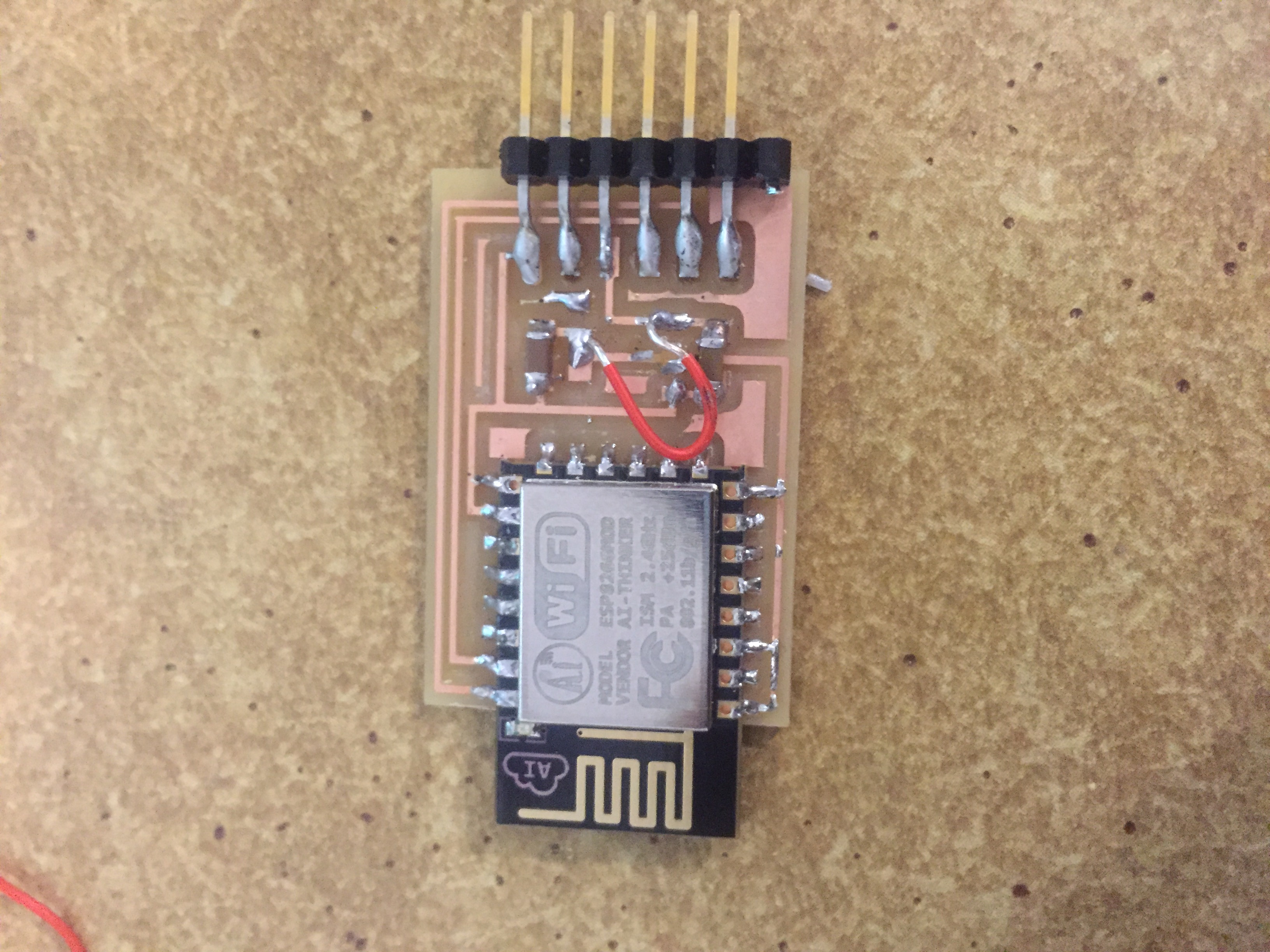
to come on Monday, so hopefully you won't be reading this sectin and I will have managed to get it to work. Here are some pictures of it. The first one is the board
itself, with a jumper cable and seeing if it works at 5 volts, the ta's said it was ok. The second one is a 3.3 voltage regulator that I made a super small board in eagle that I made of just it and attached to see of it worked. None of these worked. Also, I can drive everything to use the attiny board that I made by
myself, but I could not get it talk to wifi so I used the web page.
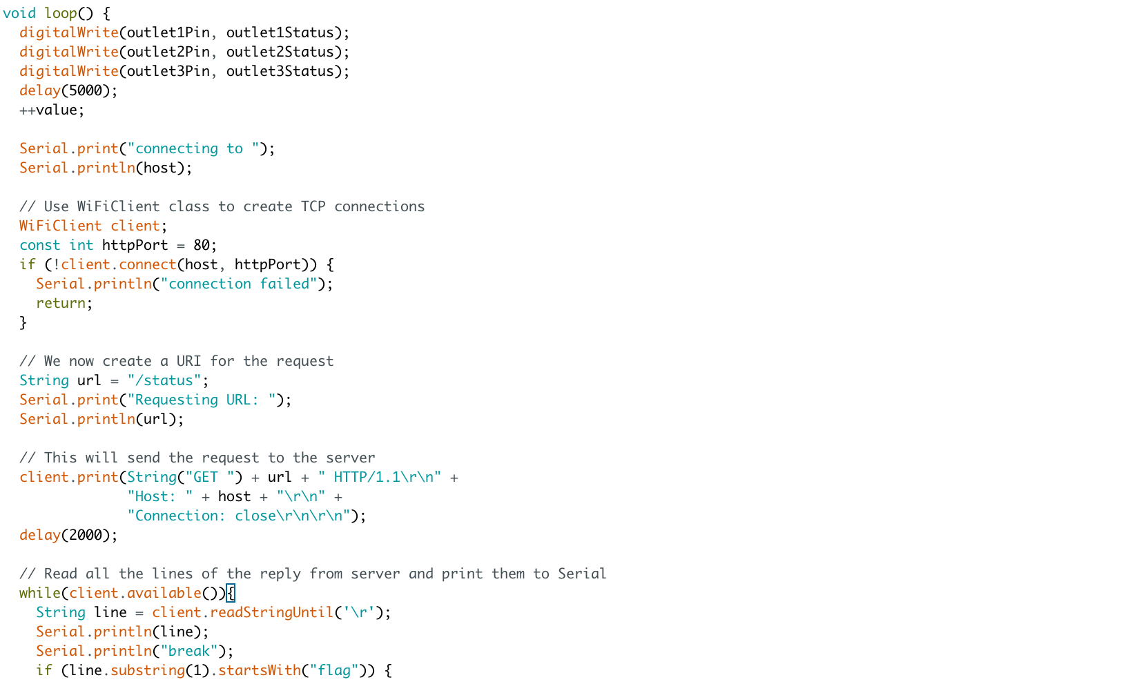
Instead, I decided to work with the lumia as picture here. The following instructions for my code are here.
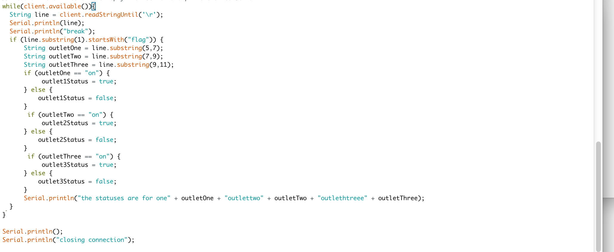
Now, that I new how to request web pages from my arduino and activate ports accordinly, I needed a way
to allow the user to edit a page and the arduino to ping it correctly. I used google app engine for this. Code snippets
and the page can be found below. I really liked how quickly it could be deployed.
Here is the video of everything completely working.