This week was the final project week! If you remember my final project proposal, I wanted to create real time, song-modulated kirlian hologram of an object streamed to a user's smartphone. The idea is that any device connected to the server can display the hologram video, upon which a user will place an plastic pyramid and see a hologram of the shocked object. To that end, there are multiple parts to this final project: (1) the box and the electronics responsible for holding and shocking the object of interest (2) the transparent electrode plate upon which the object will be shocked (3) the webcam and the processing software to create the realtime hologram video (4) the plastic pyramids and base stands to stand on the users smartphone and finally (5) the viewing boxes to ensure low light viewing (to maximize the hologram effect).
THE HOLOGRAM PYRAMIDS
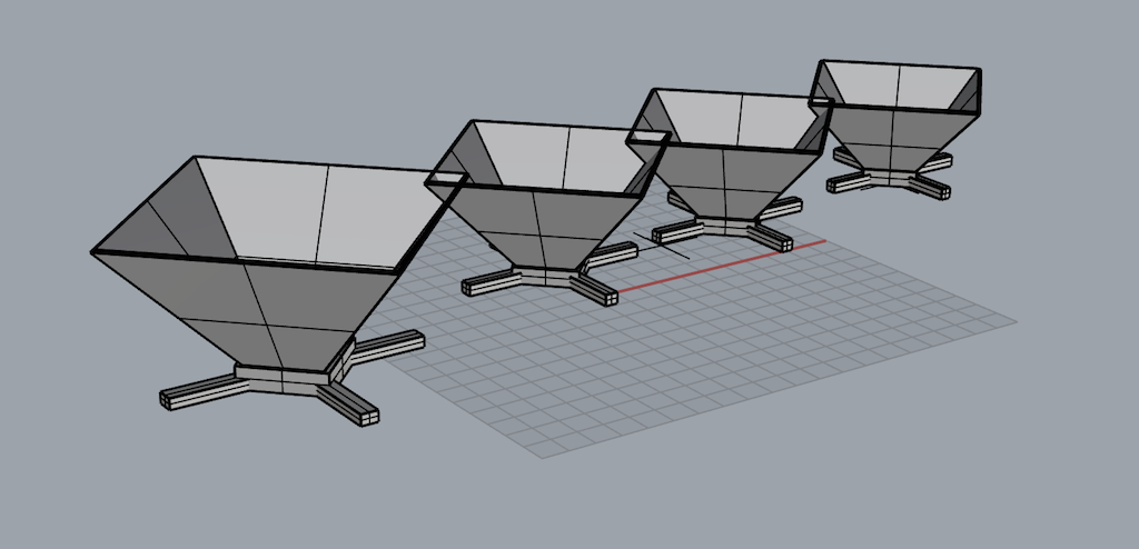
In order to create the pseudo hologram, I needed to create a thin-shelled transparent plastic pyramid. The idea here is that light will reflect off of the 45 degree planes of the pyramid onto the opposite face, which the user would be able to see as a "floating" reflection in space. So, to create these pyramids, I went into Rhino and drew up the pyramids with the TruncatedPyramid tool. The bases I made to keep the polycarbonate triangles in place, and I used the BooleanDifference command.
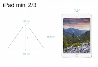
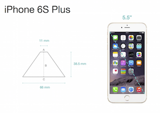
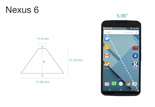
Luckily, I found an online open source set of templates of sizes of the acrylic pyramids for different smart devices. For this proof-of-concept prototype, I wanted to focus on the most popular devices: iPhone6, iPhone6 plus, Samsung galaxy, Nexus 6, and the iPad mini.
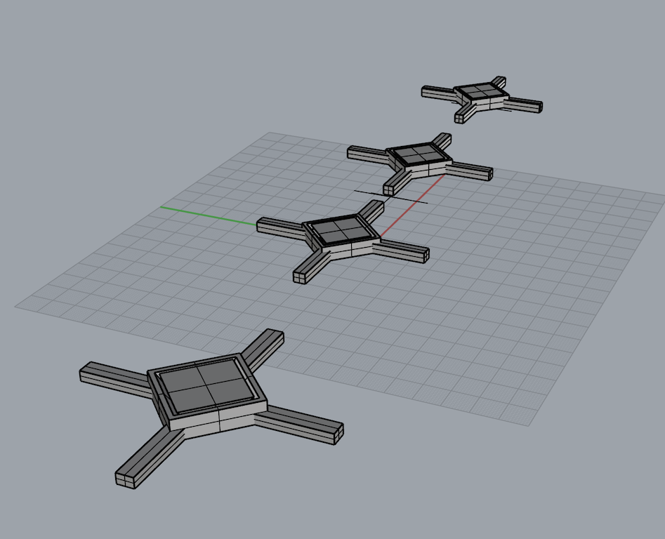
For the final bases in Rhino, I had to use iterate through the OffsetSrf command to ensure there was enough tolerance for me to insert the peices comfortable. After a few failed tries, it seemed that .15 mm of tolerance was the optimum.
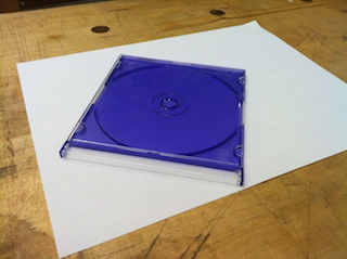
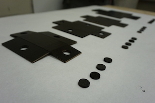
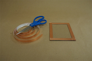
STEP 1: Get out a CD case or polycarbonate sheet.
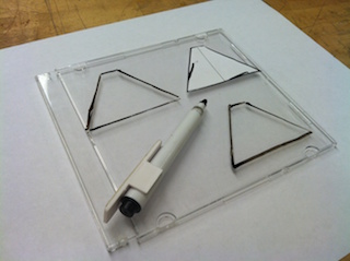
STEP 2: Mark the case with the template of the pyramid.
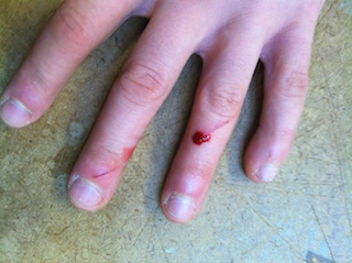
STEP 3: Cut out the pyramids by scoring with an exacto blade...but try not to score yourself.
THE VIEW BOXES
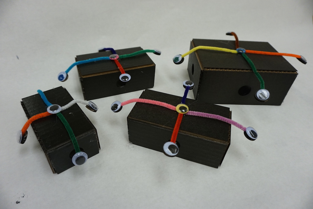
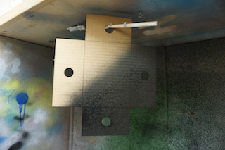
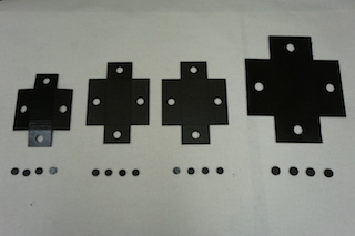
For the final presentation, I needed darkness to show the hologram optimally. But I realized that wouldn't be possible. So I made view boxes (complete with googleyes of course) so that viewers could put place the pyramid on their smart device, place on top the view box, pop out one of the google eyes, and view the hologram in complete darkness.
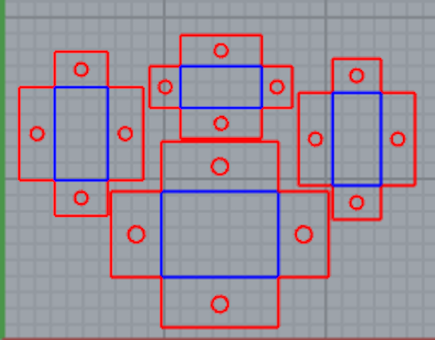
I first got all of the dimensions of the smart devices I wanted to accommodate. I then made a Rhino file for lasercutting the view boxes, where blue lines represent score marks and red represent cuts.
STEP 1: Spray paint the cardboard pieces.
STEP 2: Lay them out to dry.
STEP 3: Fold up boxes gently.
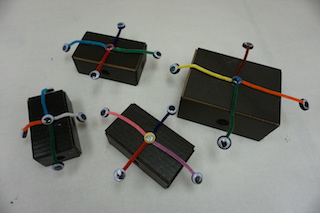
STEP 4: Glue on pipe cleaners and google eyes (for the high tech, effect right?).
THE BOX AND ELECTRONICS
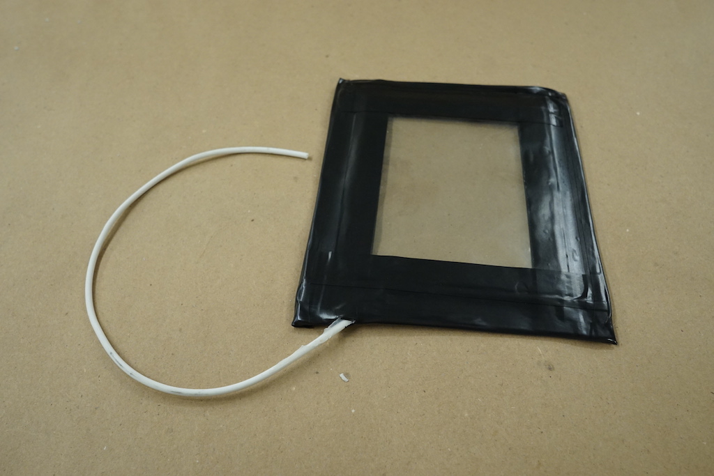
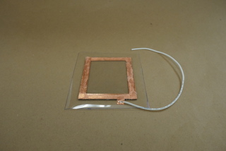
The first thing I wanted to do was create the transparent electrode which would transfer the 40,000V from the ignition coil to the object, but allow for the view to see it due to it's transparency. So I got a Indium Tin Oxide (ITO is a clear conductor) coated glass plate and began making the transparent electrode.
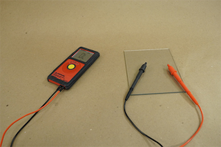
STEP 1: Test which side of the glass is conductivie.
STEP 2: Cut copper tape (1/4in) around rim of electrode.
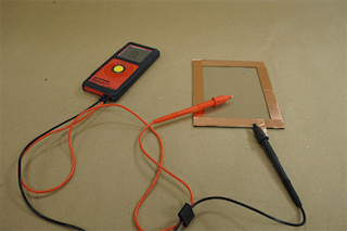
STEP 3: Ensure proper conductivity between copper tape and glass electrode.
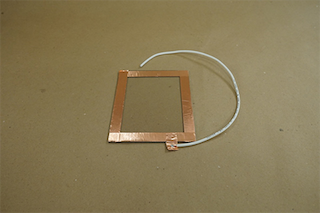
STEP 4: Solder on 18 in of high voltage wire onto a small copper tab at the side.
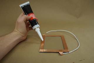
STEP 5: Add silicon adhesive to the top of the copper tape.
STEP 6: Lay down an acetate sheet FLAT onto the silcon coated electrode .
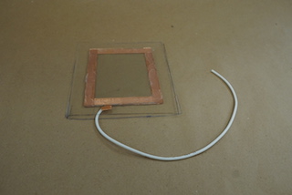
STEP 7: After drying for 24 hours, repeat on back...making sure FLAT.
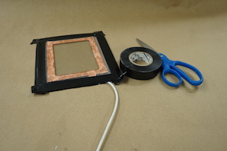
STEP 8: Cut electrical tape around the edges for insulation and protection.
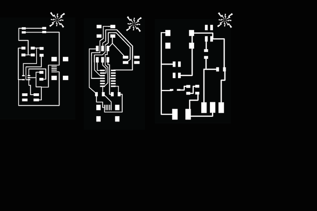
For the electronics inside the box, I wanted to clean up some of the boards of the previous weeks to incorporate any previous hacks, cold connections, loose wires, and unnecessary components. The most significant change I made was with the audioboard. Originally, I used the audioboard with an electret microphone which picked up a sound input from a speaker. But since I was limited by the gain of the opamp I was using, that I meant I would have to blast the speakers - which would be inappropriate to do for the final presentations. So, I decided to use the analog DC stereo output of my headphone speakers instead, which was about 10x higher in voltage and didn't oversaturated my mosfet. And - of course, I had to add the logo to the mill file!
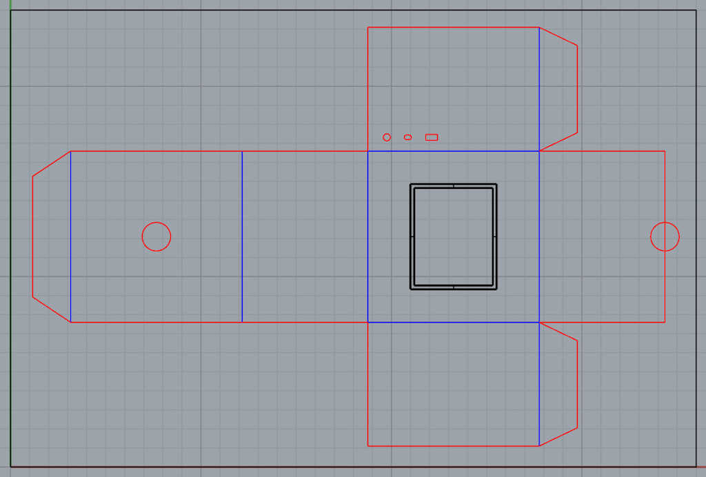
Of course, I needed an enclosuse that could both safely house all of my high voltage electronics, as well as keep the object in pitch darkness to amplify the kirlian electrophotography effect. Using rough dimensions from previous protoyps in prior weeks, I saw that a 9'' by 9'' box worked well in the XY plane and the webcam seemed to work best (in terms of autofocus) at about 6 inches of height.
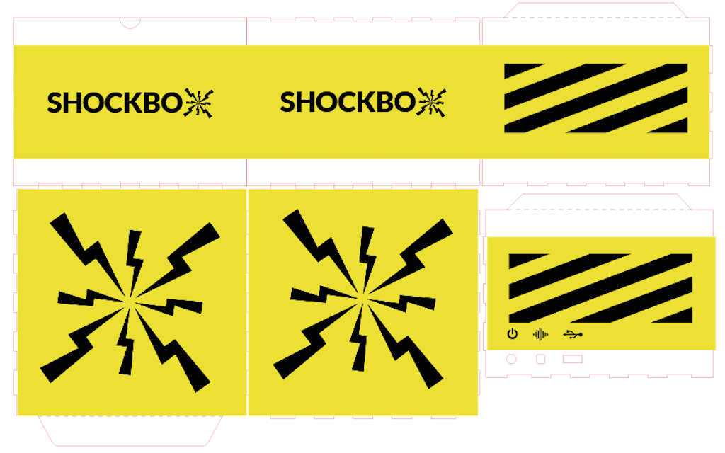
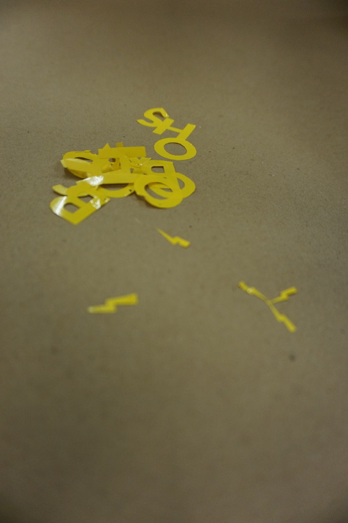
As always, branding is a key component of a successful product design. So, I wanted to make a simple brand identity based off the name I came up with, the "ShockBox"...Since yellow and black together often connote danger, I thought that would be an appropriate color scheme for a 40,000V project! I also used thunderbolts in a box formation as the standalone logo and motif throughout the sides of the box.
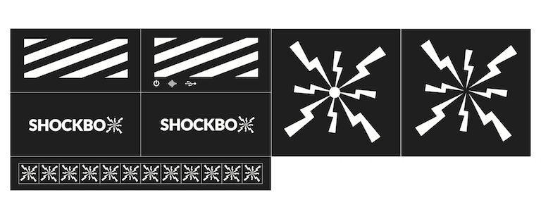
After laying out the design along the whole box, I prepared the file for the vinyl cutter in grayscale. I made sure the artboard width matched the width of the vinyl roll, an to go through a test runs to optimize the force on speed of the cutter (in the end I used 80gf and 1.5cm/s).
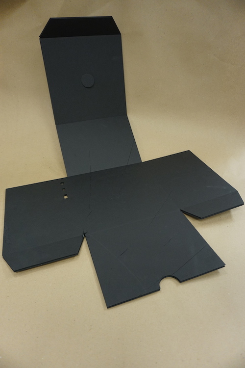
STEP 1: Lay out the lasercut board.
STEP 2: Peel off the positive of the vinyl stickers.
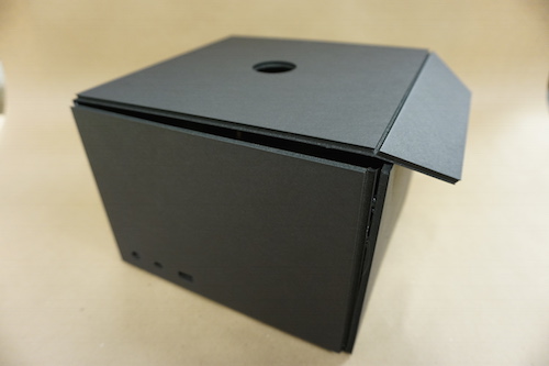
STEP 3: Fold up the box.
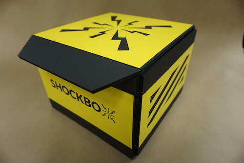
STEP 4: Add the stickers :)
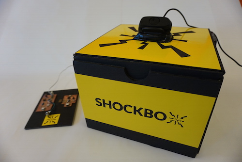
STEP 5: Connect the boards and the webcam.
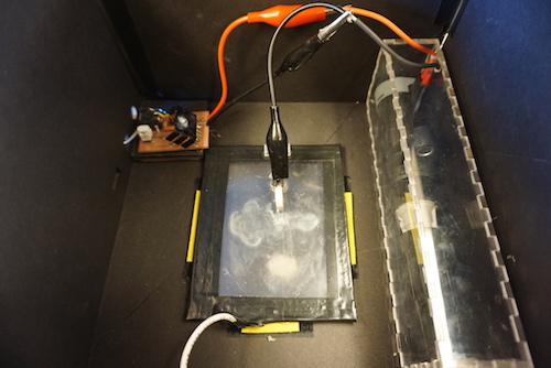
STEP 6: Add the transparent electrode plate and the ignition coil (embeded inside an acrylic box for safety).
THE SOFTWARE
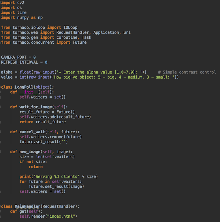
Here is a copy of the final tornado based server code I wrote up. The first thing I do is import all of the packages needed for python. I then ask the user to input two values: (1) the brightness adjustment and (2) the size of the object so that the webcam can crop down to the object. I then initiate three classes, a long poll class, an image handler class, and a main handler class - each with their own defining functions. The long poll class manages the server side, waits for an image, and prints out how many clients it's serving. The main handler class is in charge of rendering the html file, and finally the image handler gets a new image from a long-poll object and updates it to the jpg header if the stream is closed.
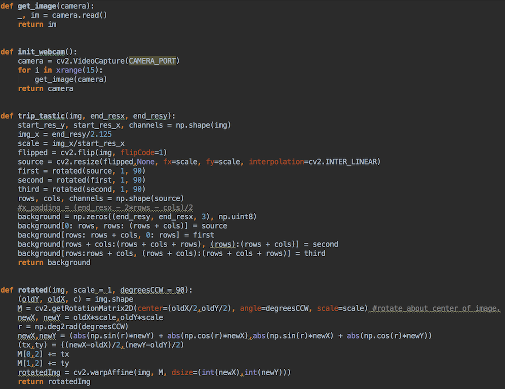
This section is the final image processing section of the server code. Here I initialize a camera capture object with opencv videocapture, I then run three functions on it: (1) triptastic (2) rotated and (3) rotate3D...Triptastic simply takes the webcam video and makes it into four reflected images, while rotated then lays out those images in a 90 degree rotation transformation from one another. Finally, the rotate3D function is the pseudo-animation which rotates the object in space with an optional skew to make it distort at specific angles.
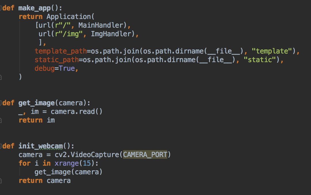
The last thing I needed to do on the image processing side was initiate the webcam, start up the app, and write the get image function for receiving the image from the camera object.
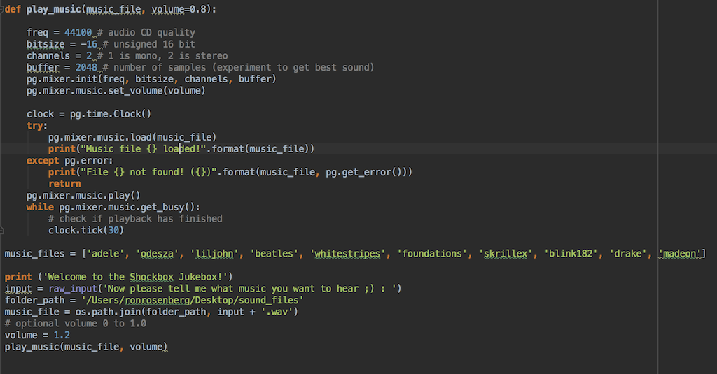
For the sound processing, I made a quick python "juke box" code as I call it that allows a user to select a music file (.wav format is best) from a "sound files" directory on the desktop.
In order to start the process, the user operating the central computer therefore would need to do two steps: (1) run the server code and then (2) run the python sound file I created which plays the song of the users choosing. Then any user connected to the same network will be able to view the hologram video at localhost:8001!!!
Once the sound program starts, all the user has to do is put on the pyramid, place the viewbox, and enjoy the show!
FINAL REMARKS
This week was a true test of integration. There were a lot of moving parts - from software to hardware to googly eye boxes - which meant that there were a lot of potential failure modes upon integrating each subsystem. It was important for me to learn this week how essential it is to go step by step, practically and logically - to deal with risks one by one. Then upon integration follow a spiral process to fix the small issues and continue to optimize each submodule - and finally bring it back together once again. It was such an incredible experience to see the key floating and sparking according to the song for the first time, and I will very much hold onto that satisfaction for a long time. I also hope to continue to optimize this device even after the class so that I can make a really polished product to put in my living room and enjoy the magic of holography, music, and electrophotography with friends.