This week, we were in charge of making a simple PCB board with functionality - in my case, a simple LED flashing on and off in response to a button push. The challenge wasn't necessarily to make the most intense PCB board possible; but rather, get comfortable with the workflow: first Eagle schematics, then Eagle boards, then milling on the Modela, coding in Arduino, and then uploading the code with the FabISP module. It was a great foundational week for future electronic projects.
IDEATION AND PLANNING
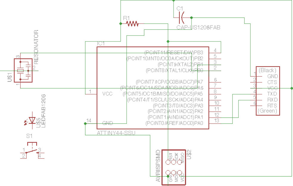
My first board was a mess. Having only used Eagle once before for a quick tutorial, I didn't know the proper and professional way to hook up connections. It only took 15 minutes for me to understand that I was hooking up my board wrong. So I quickly realized that you could label nodes, and hook them up together by defining them with the same name (use the RK100 funky icon thing on left hand side of Eagle menu in Mac).
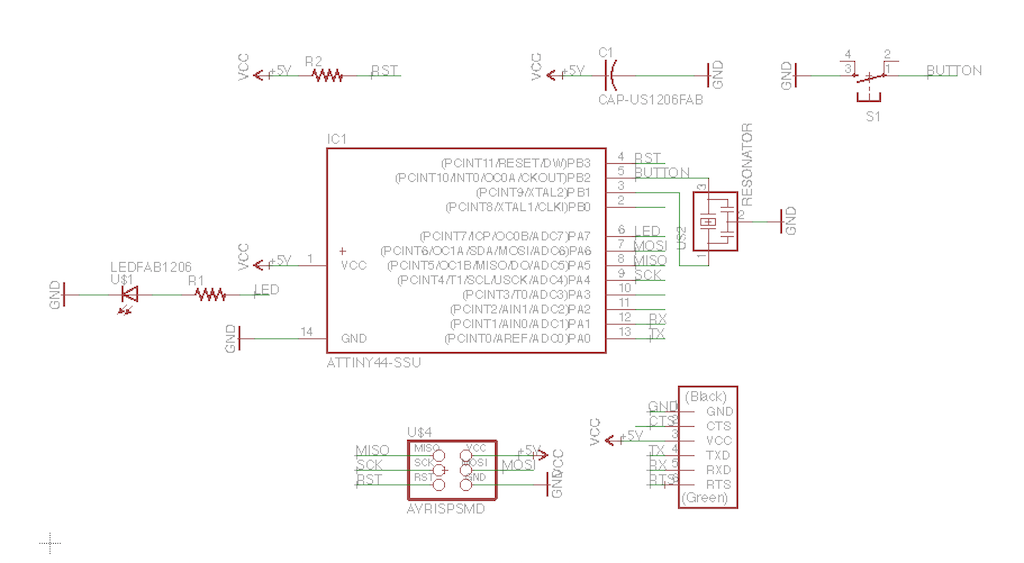
Ah, much better. Here all my nodes are connected and labeled without having to physically net them together.
With the schematic done I moved to board view (little plug-like icon on top of Eagle menu, took me years to find that!). Here I started using the autoroute function, which was cool but I actually ended up realizing hard routing it was better for space management and getting around tricky edges.

After routing the board by hand and double checking it with the ERC module (sound electrical connections) as well as the Modela-specific fab.dru DRC module (milling specific feasibility), I got a final board.
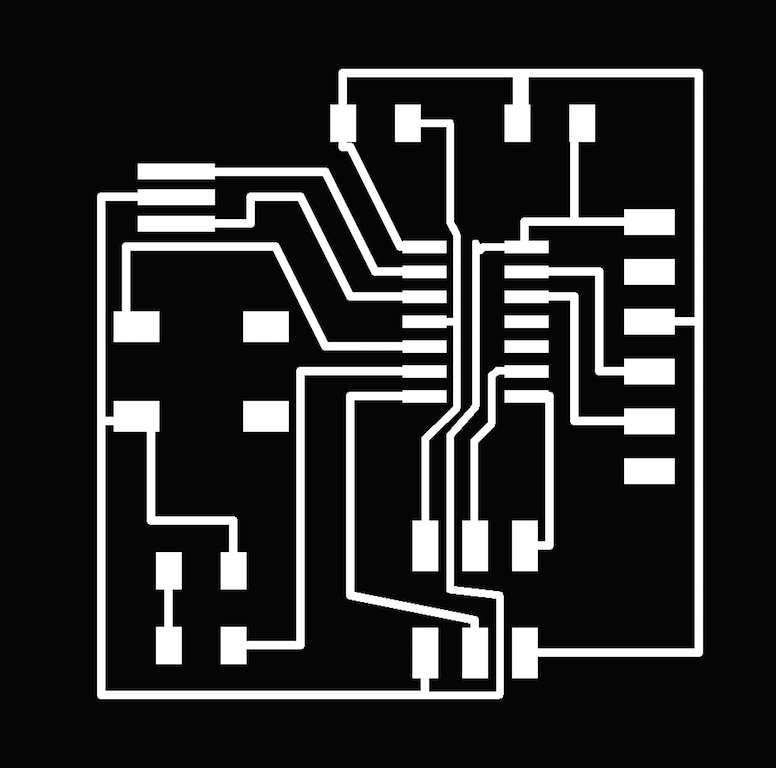
I used the "display none top" command to get just the traces, and then exported them in grayscale to be able to mill them on the Modela.I then used the "display none dimension" command to get just the outline. I made the width 0.32'' to work with the minimium endmill size of the Modela by going into Settings and changing line width.
EXECUTION

Milling the board was a bit more time intensive than usual becuase the drill bit was really dull, leading to ripped up traces. After a few tries, I got a decent board that I "deburred" with an exacto knife to make it easier to solder. Here is the full board stuffed with the FTDI USB cable attached and the rainbow wire connecting the FabISP board to my board to get it ready for being programmed.
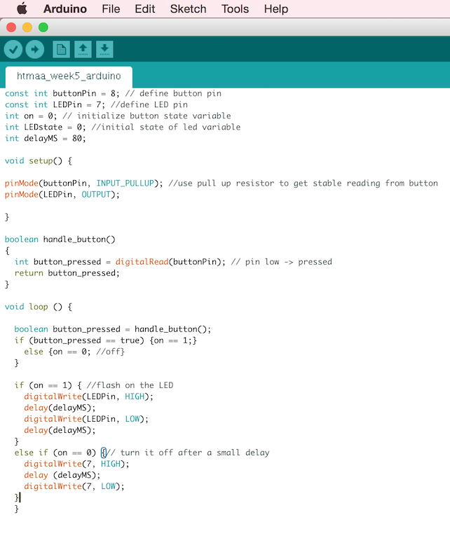
I then downloaded the Attiny packages, put them in Documents/Arduino/Hardware, and wrote up a switch button code in Arduino. I've actually done this code before so that was a fast step. I like to use a small function that I write in void setup{} called handle_button() which returns a boolean whether the the button has been pressed or not. In this way I can keep track of the state of the system dynamically.
Once the board was stuffed and the code was programmed into the board, I was ready to test! Luckily it worked on the first try and no debugging was needed.
FINAL REMARKS
While this week was rather simple, I imagine though that with more complex boards this will require numerous prototyping and spiral development through the whole process: Eagle schematic, Eagle board, Milling, Arduino, Debugging.