This week is actually quite similar to week 5 since I luckily got ahead of myself on Week 5 without knowning, and starting coding in Arduino. So I took my board with the LED and the blinking code and tried to do the same, but this time in C.
IDEATION AND PLANNING
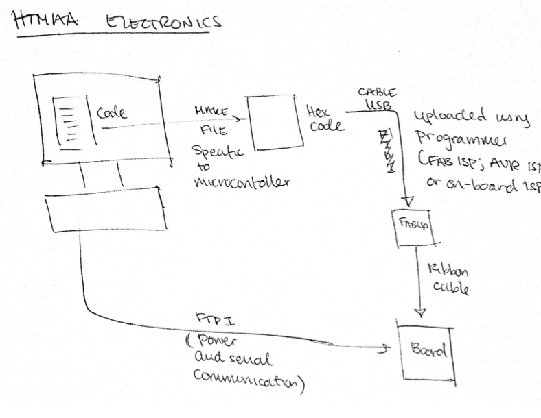
To be crystal clear about the framework, I made myself a diagram of what exactly is going on. First, code is generated on the computer (ideally, something humans can understand). The Make file is then generated; and it is essentially a simpler, board-specific version of the code written on the computer. The Hex code is then sent via the USB cable to the FABISP or an on-board programmer as is the case for Arduino boards. The ribbon cable then connects the FabISP board to the board to be programmed. The FTDI cable is connected to the computer mostly for a power source, but also for serial communication should that be necessary.
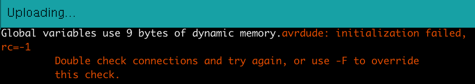
Murphy's law went into affect and the previous board I had used simply did not work. I got the rc-1 error message, telling me that there was something wrong with the connections on my board. After troubleshooting with a voltmeter, I found that my problem was in the form of two shorts - one on the 2x3 header and the other on the Attiny. I tried fixing it with copper wick, but...
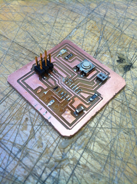
As you can see, I ripped up the fragile copper wiring, so I had to go back and remill the board :( At least I got practice on the Modela again! And thist time, I made sure to do the DRC check thoroughly to ensure my schematic was machinable. The first board I did required me going in with an exacto knife to cut up connections which were too close together, but for some reason passed with the DRC check. So I put the DRC check with a larger tolerance to find borderline jobs.
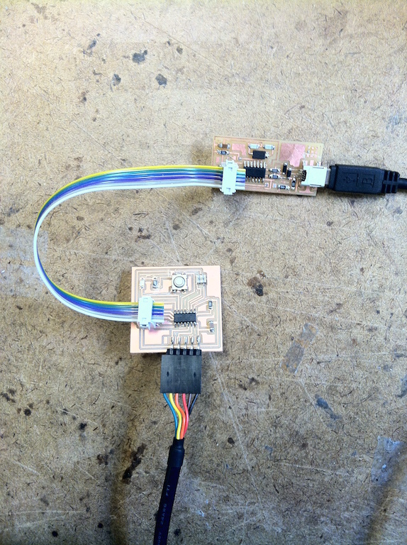
After routing the board, I stuffed it much like before, and connected the USB/FTDI cables.
EXECUTION
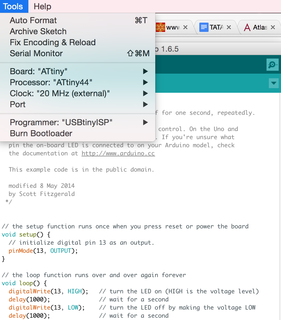
I first worked with Arduino again and did a simple blink program. It was highly important to make sure the Board, clock, programmer, and port connection were all defined correctly in Arduino. Here were the steps I took: (1) download Attiny hardware library and add into Arduino folder (2) select Attiny for board (3) Attiny44 for processor (4) 20Mhz for clock speed and (5) my USB port for the port.
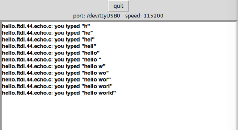
I then tried doing so in C, using the FTDI.hello.c code provided by Prof. Gershenfeld. The steps I took were the following: (1) open terminal and navigate to folder with ftdi...c code (2) write "make -f hello.ftdi.44.echo.c.make" to make a make file for the hello.echo.c code (3) "sudo make-f hello.ftdi.44.echo.c.make program" to program the FabISP with the make code (4) "sudo make-f hello.ftdi.44.c.make progam -usbtiny" to program the microprocessor (5) "python term.py/dev/ttyUSB0 115200" to open a python terminal with the communication from the microprocessor.