This week I wanted to get started on my final project - the Kirlian Photography hologram machine. As part of the machine I need to establish a high voltage (>1kV) signal to shock my sample and ionize the air around it. So, I decided to make an ignition coil driver circuit, one which would output squarewaves of variable frequencies and duty cycles which would drive the ignition coil and create a high voltage output.
IDEATION AND PLANNING
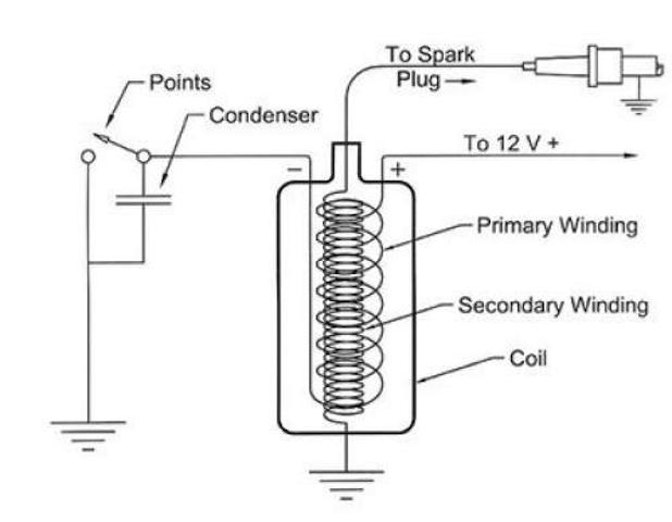
First, I needed to review how ignition coils work. Ignition coils are inductive coils that amplify a voltage input proportionally to the derivative of the current. In cars, this is done manually, generating a spark at the spark plug which ignites the ignition of the car. Here, I decided to do it via Arduino, with the switching on and off dictated by a squarewave output of anywhere from 0-200hz.
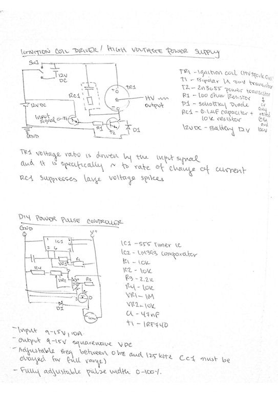
I started sketching out different circuit design iterations, trying to balance simplicity with robustness. Given that this is a high voltage experiment, I decided to design in a few key features: (1) separating out the hardware and the softare into two boards to protect the arduino (2) add an emergency stop switch on the software side (so that I don't have to touch the hardware board) (3) add a capactivie RC circuit to absorb any inductive leakage once the coil is shut off (4) add a diode in series with the drain gate of my MOSFET to ensure no leakage current flows back into my MOSFET.
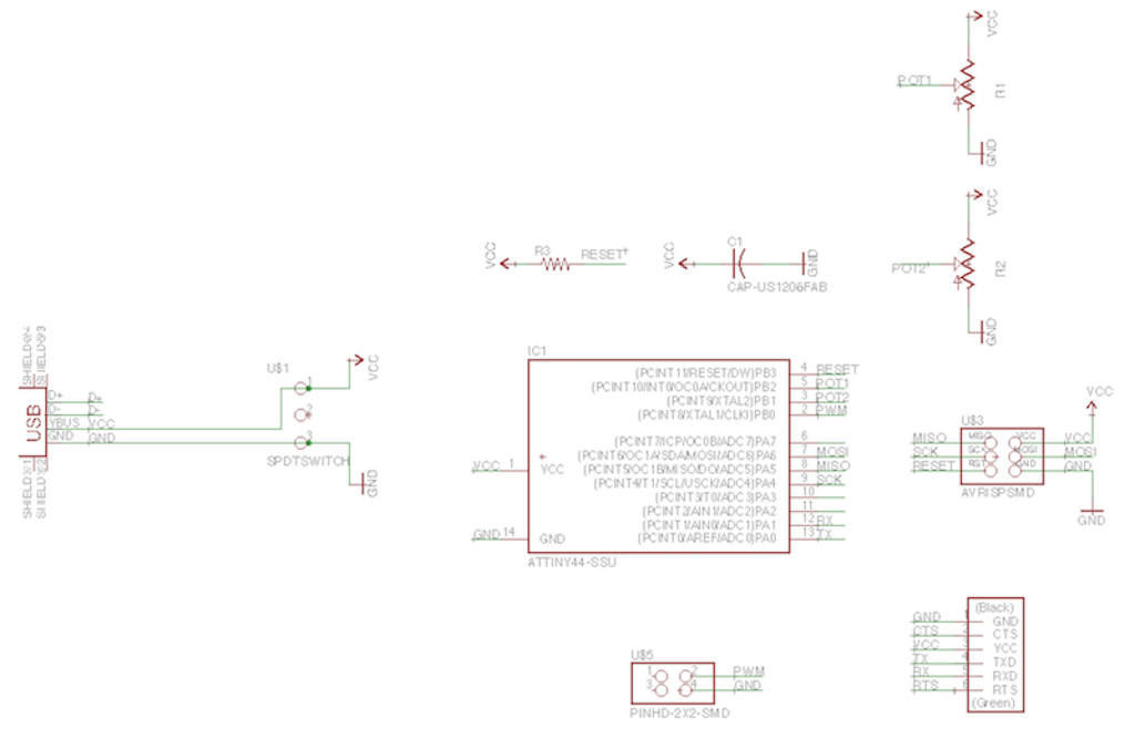
The arduino board circuit schematic. Here, I notably have two power sources: the FTDI and the USB mini. I did this so that I would have the option of powering the board at home with my USB mini cable or in lab with the FTDI cable. I also simplified the design by using the 8Mhz internal clock of the Attiny rather than adding the 20Mhz crystal externally. The PWM signal comes off of pin3 and the button is controlled (along with an internal pull up resistor) on pin2.
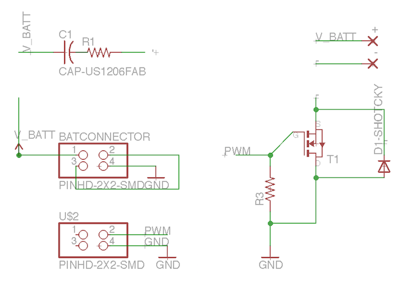
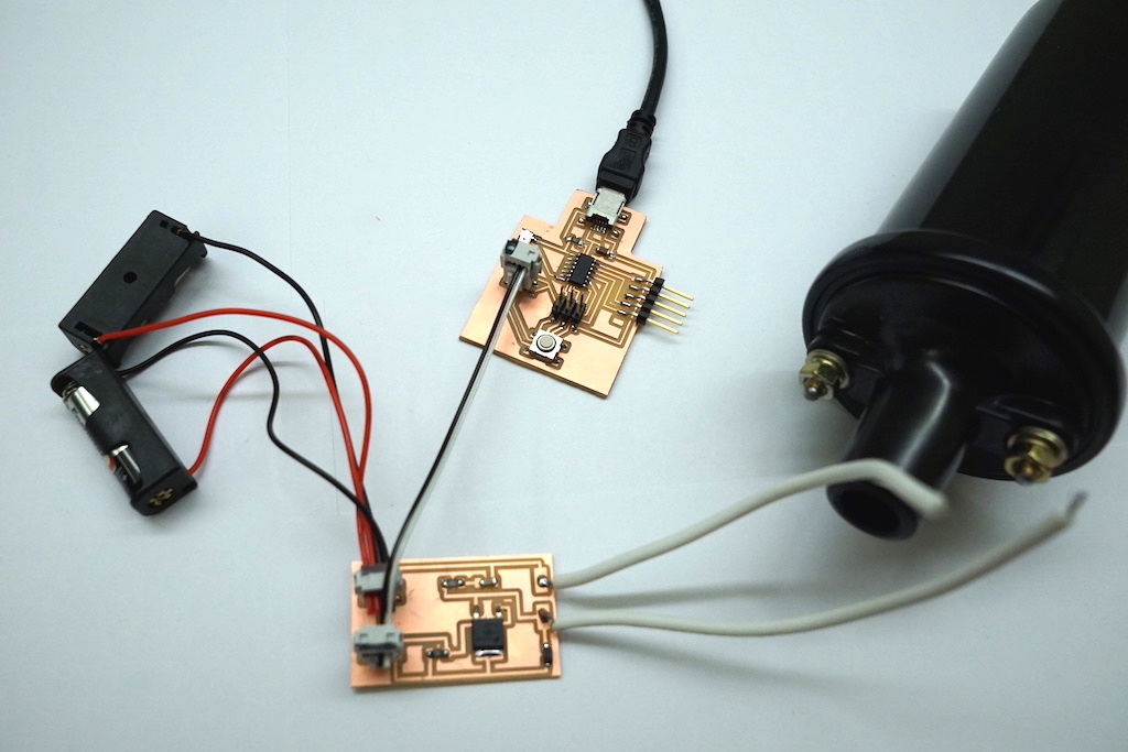
The driver board circuit schematic. For power, I started by connecting two 12V batteries in series using a 2x2 header and ribbon cable but then moved to a 12V, 6A powersupply which could provide more current to the ignition coil (and larger spark potential). The PWM signal from the Attiny on the arduinoboard is sent to the gate of the MOSFET. The differential 5V voltage between the gate and the source turn the MOSFET on and off, allowing current to flow from source to drain (for the NPN transistor I am using). Thus, when the FET is "on" I get 24V between the + and - of my load, and when it's off I get 0V.
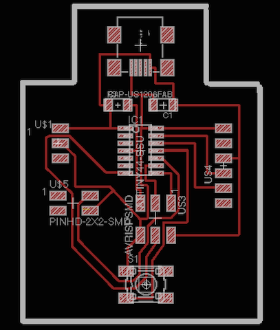
The arduino board circuit board diagram.
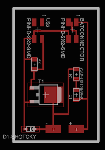
The driver board circuit board diagram.
EXECUTION
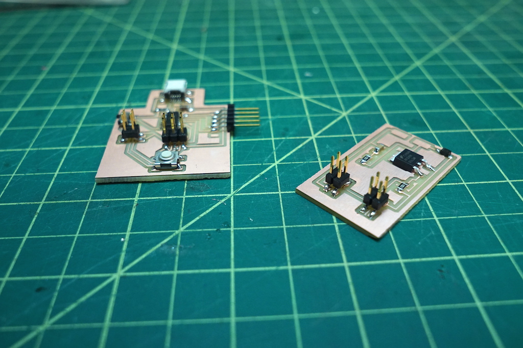
Milled boards. Notably, I changed the modela settings from 0.4 mm for the 1/64 endmill to 0.3969 since I noticed some of my traces were getting combined. Also, to acommodate for a small tilt in the base sacrificial board, I increased the drill depth to 0.2 mm and decreased the speed to 2 mm/s so as to keep the small material removal rate.
I originally just tested my arduino PWM code to see if I could generate different square waves of different frequencies after the actuation of a button push. This worked out right of the bat, but for the driverboard...
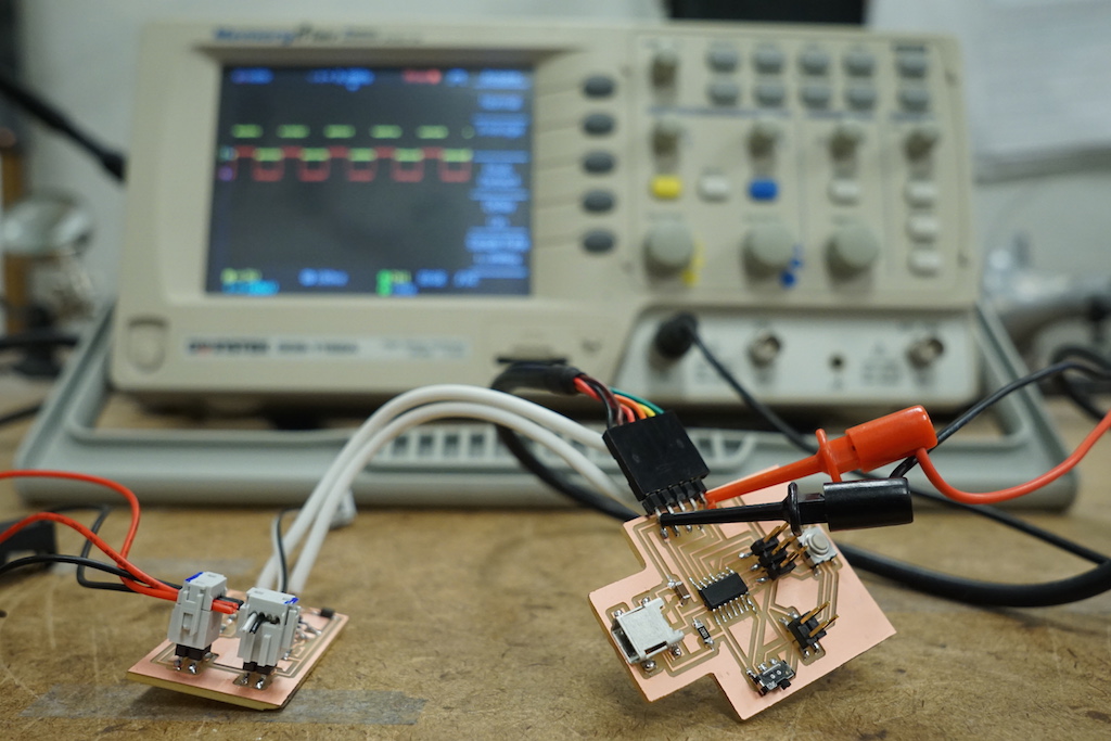
When I first tested the driverboard, my MOSFET immediately glowed burning hot and I got no response from the output. Looking at the data sheet, I checked (1) whether the 0-5V squareave voltage between the gate and source VGS, was sufficient to switch on the MOSFET...it was (2) What the maximum current rating of the MOSFET was...8A...below the 6A that it was experiencing with the 12V, 6A power supply. Things seemed to work out on paper, but I suspected that I had underrated MOSFETS because they kept frying.
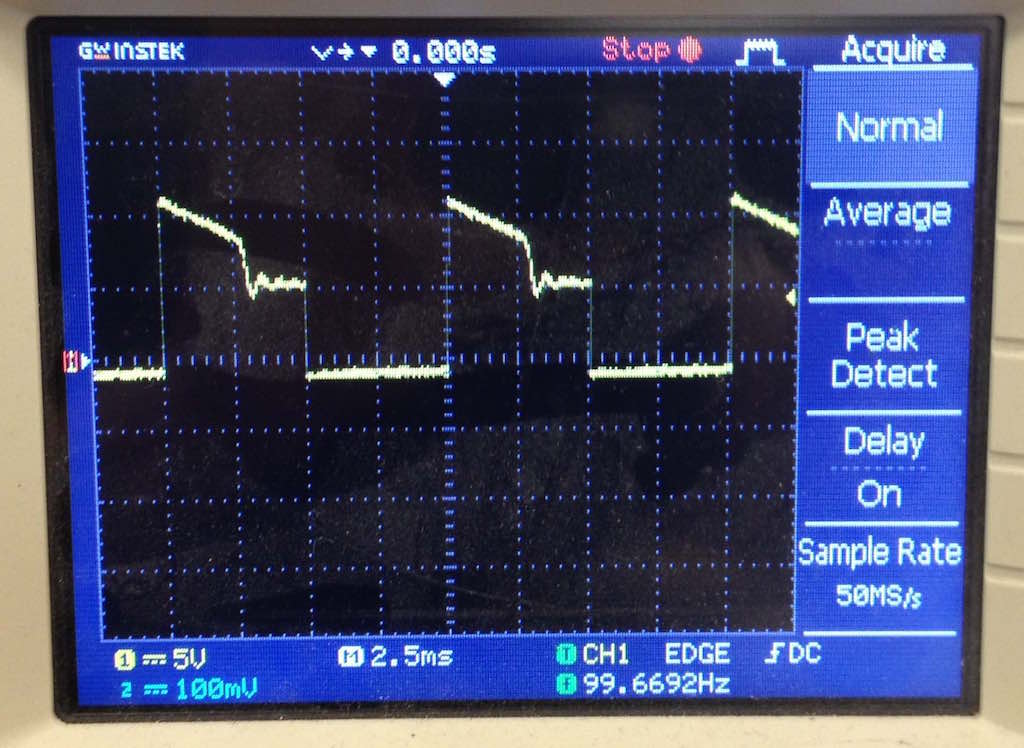
To test this hypothesis, I put two MOSFETS in parallel, and saw this response. A significant improvement of the output but still an odd decrease in voltage from 12-10ish volts.
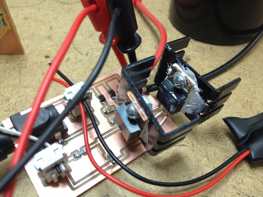
So now let's add three MOSFETS in parallel, and connect them to a heat sink with a small screw, a nut, and thermal conductive paste...
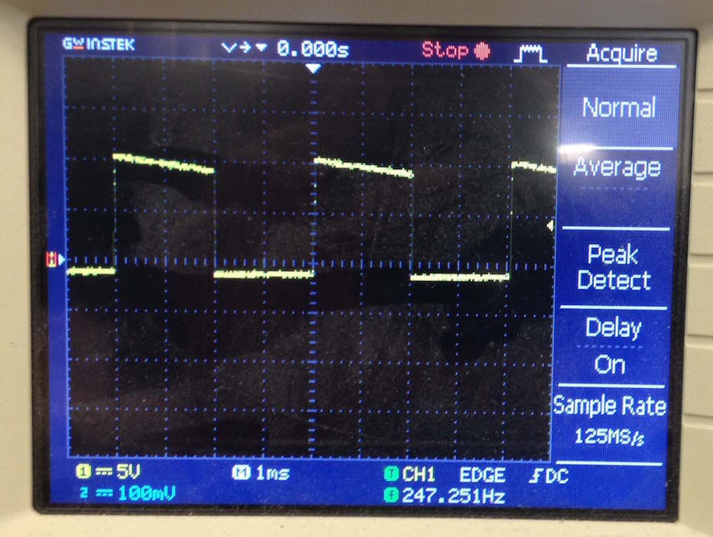
And now the correct response desired! By reducing the current thorugh the MOSFETS by a third, the MOSFETS were able to remain cool to the touch and work properly!
But after hooking up the ignition coil, there were no sparks! What to do now...Was it the ignition coil? I resistance of the primary (10 ohm) and secondary (10k ohm) coils and it was within spec. I resoldered the connection to the HV output of the ignition coil. I checked again whether the MOSFETS were fried (by seeing if there was a short between G and S)...and everything checked out. After hours and hours and hours of trial and error, it became clear that the problem with the circuit was the second diode in parallel with the ignition coil, the diode not in series with the RC. By having this diode without an associated RC snubber, it was effectively creating an open circuit when the ignition was driven at high voltage. Thus, no sparks were forming. So I redrew up a circuit diagram and remilled the board without the second diode.
And now the ignition coil worked! A 30,000+V pulse comes out of the high voltage terminal and ionizes the air between it and ground. I got upwards of 6cm arcs! I now attached an object to ground and put it between an insulator and a conductor attached to the HV terminal. Now the air will ionize around the edges of the object. For a preliminary test, I used a quarter coin, shocked at different frequencies to see the effect.
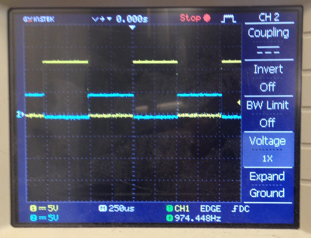
Low frequency: 100 hz squarewave, 50% duty cycle. Sparks are more sparse and defined.
Higher frequency: 10000 hz squarewave, 50% duty cycle. Sparks are more "fuzzy"!
FINAL REMARKS
This week invovled a LOT of debugging. I learned a few super important things with regards to electronics debugging: (1) always check the data sheet (2) always bring a copy of the schematic with you to check out while trouble shooting (3) be wary of shorts (4) "follow" desired signal throughout circuit to see where it is not acting as desired (5) look up how to confirm proper operation of components, specificaly diodes and mosfets and finally (6) always use a scope! Next week I hope to take this concept further and marry it with my original concept of taking in a song input to drive the ignition coil.