This week I wanted to add the sound element to the kirlian device - that is, have a sound input replace the square wave and drive the MOSFET, and thereby the ignition coil.
IDEATION AND PLANNING
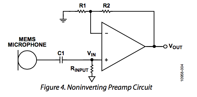
I first realized I needed to create an amplifier circuit. So I studied how op-amp amplifiers work in both inverting and non-inverting modes for audio amplification. I also looked up the spec of the electret we used and realized that it works off of capacitance. So that means that with a capacitor in series as in the picture above I had to be sure that the capacitance was on the order of that of the elecret so as not ot create a "capacitance divider" and mute the signal of the electret.
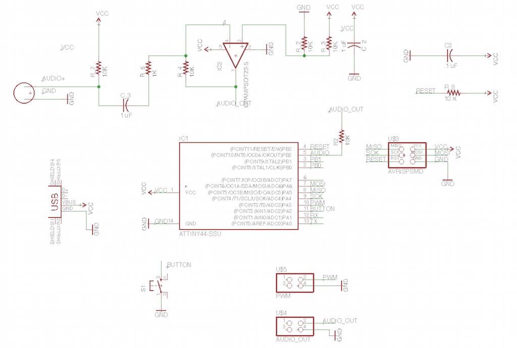
The new arduino board schematic. This time it incorporates a DC analog electret microphone and gets rid of the FTDI port. The input sound goes through a inverting amplifier circuit, with a gain of 100 (1K of R1 to 10K of R4). That audio output goes either to the 2x2 output header designated Audio out or it goes into the ATTiny in case I need to do future further processing of the signal, from where it would come to the 2x2 header named PWM.
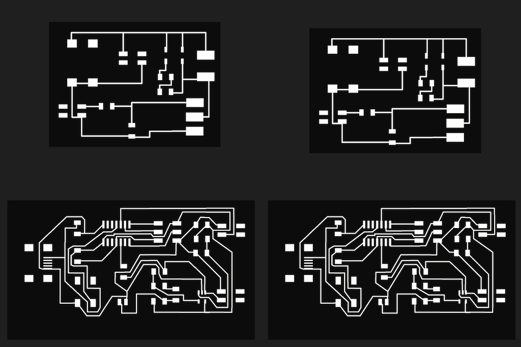
The arduino board circuit traces along with new version of the driver board. In order to maximize thorughput, I put the eagle PNGs into illustrator and made a file the size of four boards. That way I only needed to drill once, rather than four individual times.

The outlines. Making sure to invert the photo with the modela so that it milled the line, and not the inside and outside of it.
EXECUTION
Testing out the output response with Adele's new song, "Hello". The amplifier originally just ouput 2V maximum; so I increased the gain 5x and put on the 500K resistor in place of the 100K. Then I got the high enough voltage to drive the MOSFET.
FINAL REMARKS
This week definitely served as a good proof of concept of the ability to use an inverting amplifier to drive the ignition coil. For next steps, I may want to actually input the audio signal into the Attiny and perhaps do a FFT on it to vary the audio output. I also think I am going to change the RC component so that it doesn't become a low-pass filter since I can see that high-frequencies are not passing through as much (i.e. Adele's voice versus the bass in the background).