Portfolio

Getting Started
Building this Website

Week 1
Final Project Proposal

Week 2
Press-fit kit and laser cutting

Week 3
Electronics production

Week 4
3D Printing and Scanning

Week 5
Computer-Controlled Machining

Week 6
Electronics Design

Week 7
Casting and Molding
Week 8
Embedded Programming
Week 9
Output Devices
Week 10
Input Devices

Week 11
Interfeace Programming

Week 12
Thermoforming

Group Project
Drink Machine

Final Project
Task Pad
About
-

2015-2016
MS in System Design and Management
The program is jointly offered by the MIT School of Engineering and MIT Sloan School of Management. I am working on complex systems with a focus on industrial applications of IoT.
Getting Started

1. Website Template
In this post I will show you how I've built this website - Good for beginners. I started by looking up some of the tools suggested on the class website and ended up exploring two options; HTML5 and Bootstrap. After some testing I picked a BOOTSTRAP template and customized it for my needs. The downloaded package comes with the html, js and css files for the template to work nicely. For a step by step tutorial on customizing the html I found these VIDEOS useful.
2. git and class repository
Download git: If you are using a Mac you need to get homebrew in addition to downloading git. This will allow you to use bash commands. I also found out that there is a Homebrew Cask that allows you to download Mac desktop apps. This will come in handy when we will need Gimp to resize pictures for he web. There are general configurations we can set up with git, only once. Here is the list you should type in the terminal:
$ git config --global
(comment: for user config)
$ git config --global user.name "Firstname Lastname"
(comment: set name for commits)
$ git config --global user.email "address@site"
(comment: set email for commits)
$ git config --global push.default simple
(comment: default push only the current branch)
$ git config --global core.editor vim
(comment: set the editor)
$ git config --global pull.rebase true
(comment: rebase rather commit automatic merges)
Security: Public keys were shared with the class and need to be saved in the .ssh folder. The folder is hidden and settings need to be adjusted to see it. It can be crated from the terminal with the following command $ mkdir .ssh. In the same folder we need to create a config file it can be done from the terminal with the following command $ vim config. Once open the information about the server can be added. To save the file you need to press "ESC" followed by ":" followed by "wq" for "write and quit".
Repository: The first step is to clone the repository from the central server with $ git clone repo.info... Then navigate to the cloned directory on the local computer, then to the people directory and finally to your name. The folder contains an empty "index.html". Assuming that you have already worked on your html template you can now save your .html, css, js and image folders in here. Now we are ready to push the new changes to the remote repository. We have to use a number of commands to push these updates:
$git pull
$git add --all
$git commit -am “comment"
$git push origin master
More generally to get familiar with git basic commands I used this WEBSITE.
Week 1
Final project proposal
My initial idea for the final project is to build a device that can detect and id wireless sensors in close vicinity and display the infomration on a dashboard. The aspect of Industrial IoT I am most interested in is around machine to machine communication and more generally around smart machines. The area of application I chose is advanced manufacturing and I started focusing on some of the issues in this sector. According to the Digital Manufacturing and Design Innovation Institute "Many machines used on the shop floor collect data but cannot make “intelligent” decisions in response to variations, disturbances, machine and tool deterioration, etc. They are also not capable of performing self-monitoring or self-correcting functions, or adapt to variations in real-time. As a result, there is a longer time to market, loss of revenue, and inconsistent product quality." I followed 3 threads:
 Source: libelium
1- Human machine interaction: A machine that can guide the user on how to operate it. Using an RFID on the machine that contains the correct sequence of operation. The operator would have a device that guide him/her based on the programed steps. In essence it is the machine using the human to self-program, this takes advantage of the dexterity humans have and machines do not.
 source:ITbrief.co.nz
2- Self-aware: Allowing a machine to know its position using a combination of internal sensors and environmental sensors. But position is rarely the issue (except for applications in logistics and transportation). Most likely the parameters of interest would be feed rate, use cycles, temperature, pressure...etc. This is harder to do without sensors inside the machine unless we can propagate the information to the external surface. What would be interesting to explore here is the another type of sensing; network communication.
3- Self-correcting: It can compare its current condition (self-aware) compare it to its own baseline or compare it to similar machines around it. Here we can imagine embedding sensors via additive manufacturing in the components, that allow the collection of data. This can be self-repostitioning or self-healing or self-reconfiguration.
Week 2
Press-fit kit and laser cutting

The assignment was to design a kit and laser cut the pieces using card board. I started by surveying the different tools for the design of the kit.I wanted to try out a new software for this week and Rhino 3d had been on my list for some time. Antimony seemed like it would be a great option as well but the tipping point was the much easier laser set up using Rhino. On top of that Rhino is a good rendering tool and I plan on using tha option later.
I started with two options:
(1) Design a mosaic kit that can be assembled together and painted to create custom designs. I have always been interested in these simple geometries that can be combined to form more sphisticated patterns.
(2) Design a kit comprised of gears and support beams that can be assembled into a moving structure. I was picturing a moving caterpillar driven by the first gear.Eventually parts of the moving structure could be lifted up to make it reach or climb stairs.

 I decided to go with the second option as it had the potential for more interesting automation in the future.


Week 3
Electronics production
1. Overview of the PCB Design


The assignment for this week was to produce a PCB - Printed Circuit Board. Using the provided circuit design the goal was to machine cut the board with a milling machine. Then stuff the board with the list of components provided this of course included soldering. Finally the we needed to program the board so that it can be used in subsequent tasks to program other boards. If everything is done correctly, the board is recognized by the computer as a usb drive.
2. Set up of the Milling Machine
Usig the fabmodules, it was fairly easy to select the traces and contour images to be milled. The important settings (after selecting the right picture.png)are to chosse the Roland Mill in the process page and the type of cut (traces uses 1/64" or contour 1/32"). For the traces the depth of cut is 0.12" and everythign else is set up by default in the fabmodules. Next we need to put in place the milling bit, position the milling head at the (0,0) position (bottom left corner) and measure where the milling starts to set the initial (x,y). Once the head is positioned, we can lower the drill to until it is about 1/8" from the surface of the board (using the buttons on the miling machine front panel. At this point we are ready to loosen the screw holding the drill bit until the head touches the surface. We are ready, select "Calculate", then "Send".


3. Board Stuffing

For this step we need to gather all the components that go on the board (see full list at the bottom of the page). A good practice is to print out a list of the components needed and use double sided tape to tape them on the sheet as shown on the picture. Check directions for the diodes and microcontroller when placing them on the board.


Marks on the diodes (representing the cathodes) should be on the right on the picture and the mark on the microcontroller should be on the top left.
Soldering takes practice. It is better to start with the hardest components first. In this case I started with the usb tiny components as it has many (very small pins). I then moved from top to bottom and from center to edges. If you have to go back to the center of the board there is a risk of frying your components. The flux pen pictured above helps getting the solder to stick to the pins only, any excess solder can be removed with a copper wire mesh by reheating the area. The board itself was fixed to the table using double sided tape. The flux pen was a great help in this step.
Board Testing: Once the this step is done we need to test the board with the multimeter to make sure there are no closed or open circuits that are not supposed to be there. With the multimeter (voltmeter) we can test two ends that are connected via a soldered component, it should read a non-zero resistance since the component itself would have a resistance. As a reminder, an infinite resistance means open circuit and 0 resistance means a short circuit.
Troubleshooting the board: "If you have successfully programmed your device, but it is not recognized as a USB device, that means that the connections between the tiny44 and the programming header are OK, as well as connections to ground, vcc, etc. The problem must be in the upper part of the circuit. Look for diodes backward, bad solder joints on the resistors connected to signal paths, shorts between usb leads, bad connections to the usb signal pins.One way to diagnose is to find a working programmer and probe signals with voltmeter and with scope. On a working model, you will see signals from scope and from the tiny44, and the 3.3V level defined by the zeners. You can use the comparison to tell you where the problem likely lies." I had to apply excess solder to the usb connections area and remove the extra with the copper mesh.
4. Board Programing
In both stuffing and programming, testing is key. Once the smoke test is passed, the board needs to be programmed using an in-system programmer (AVRISP mkII) in this case.For this I followed a step by step tutorial. Here I will summarize the main steps for Mac:
1- Set up path
2- Install Crosspack AVR
3- Download firmware
4- Enter the following commands in the terminal in the firmware folder: make hex, make clean, sudo make fuse, sudo make program.
If your FabISP has been successfully programmed, you should see it in the list of the USB devices plugged into your computer.
- Date: September 2015
- Skills: Soldering, Circuit testing
- Time: 12 hours
- Supplies: Milling machine, 2x (100ohm resistors)
Week 4
3D Printing and Scanning
1. Model Design

The assignment for this week was to design and 3D print an object. I chose to go with a "Klein Bottle", a methematical surface that is non-orientable."It is a two-dimensional manifold against which a system for determining a normal surface vector cannot be consistently defined. Informally it is a one-sided surface which, if followed, from the point of origin and back would flip the traveler up-side down."


I designed it with Rhino 3D starting from a 2D hand drawn profile and using the "revolve" option to obtain the outer surface. I then added points along the inside of this surface to form the inner surface. Becasue this inner surface is not symetric in one of the planes, the "revolve" option did not work and I had to work with "offset" and control points to manually adjust the shape. The hardest part was closing the final polysurfaec surface by joining the two separate surfaces. A view of the mesh quickly reveals the areas with problems. One of the issues was the difference in shapes of the top and bottom junctions.
To help with the joining of the surfaces I created a new shape with circular top and bottom openings.


This new approach worked better but Rhino 3D was still flaging the polysurface as an open one (which does not work for 3D printing).Using "ShowEdges" and creating a small surface allowed me to join the inner and outer ones.
A huge Thank you to our TA Ines for her help debugging this model and joining the meshes!
Because this Surface a has a nice mathematical representation I wanted to experiment with "Antimony". Using the implicit "equation" and the "script" option in Antimony, the surface can easily be defined.


2. 3D Printing
For this step I used the Ultimaker 2 with the Cura software. Testing with the following settings:
- Test 1: 70% of the nominal speed for the first layers and 100% for the rest. Th eprocess lasted 2hr:30min with a fill density of 20%.Height of 7.5 cm.
- Test 2: 100% of the nominal speed for the first layers and 150% for the rest. The pringintg process lasted less than 2hrs with a 0 density fill. Height of 10 cm.


The results of the 3D printing are not toally satisfying as Cura (the 3D printing software removed the inner surface and printed an empty object.
3. 3D Scanning
I experimented with two different 3D scanning tools; (1) the Sense scanner and (2) 123Dcatch an iphone app by Autodesk. The sense gave better results and was faster.


- Date: October 2015
- Skills: Desing
- Time: 12 hours
Week 5
Computer Controlled Machining

1. Model Design
The assignment for this week was to build something big with a computer controlled machine using either OSB, ply-wood or foam. I chose to go with a "zero gravity chair", a chair that allows you to recline to almost 180 degrees. Here are a few inspirational pictures.


I designed it with Rhino 3D starting from a 2D hand drawn profile.


Meet the Onsrud, our tool for this week!

The Cut started out nicely but it did not last. Some of the smaller pieces were too close and started coming out off the board on the last pass. This last pass was supposed to cut through the last layer, it was thicker than the onion skin anwas menat to give a nicer finish. We had to stop the Onsrud when pieces started flying off so the remianing pieces were not cut all the way through.


- Date: October 2015
- Skills: Desing
- Time: 12 hours
Week 6
Electronics Design
1. Model Design

The assignment for this week was to design an electronics board , mill it and stuff it. I started with the following tutorial Electronics Design 101, for this assignment.
After installing Eagle, the software used for the PCB design. Next we need to add the following libraries:
- Add fab.lbr, a library of modules created for the class assignement.
- Add fab.dru.
Using a right-click we need to add these two files to the "lbr" folder in the Eagle directory. Once tht is done we can go to Eagle, File, New project. In the new project, open new schematic. Once that is open, click on the icon next to "1/1" in the top menu. Use the "Edit" and "Add" to add new components or the "Add" icon on the left menu.
The list of components to add is the following:
- fab/attiny44-ssu.
- fab/res-us1206fab.
- supply1/+5V.
- supply1/gnd.
- fab/resonator.
- led/ledsmt1206.
Project View

Library View

The procedure to wire them is the following:
Use net to wire them together.
Protip: move parts to check if they are connected.
Save and switch to board view (tiny plug/chip icon upper left next to 1/1 button).
Drag components to where you want them to go.
Use route (blue line icon) to connect components.
Protip: Hit ratsnest (starburst) to check if everything is connected.
Protip: Hit DRC (green check) to see if traces are millable. If the traces width is too small, the DRC check shows a warning.This is importnat for a given trace and for clearance between traces. Using the "change" (wrench icon)tool on the left hand-side tool bar, you can set the width of the traces. For the traces there needs to be enough clearance(1/64"~0.016) and for the contour (1/32"~0.031).
Drag dimension outline to be a snug fit around board.
Type display none dimension into command box at the top to see outline.
Export as grayscale 600 dpi png for cutting out interior of board, display none top to see traces.
Export as grayscale 600 dpi png for milling traces.
Schematic View

Board View

Contour

Traces

2. Board Milling and Stuffing
Once the board traces and outlines are set, the milling is done with the Roland Mill machine using the fab modules - See Week 3 for more details. Here is a short list of the steps:
- Open png image
- Select Roland Mill process
- Select traces (or outlines)
- Set the cut depth to 0.12 and (x0,y0,z0) to the right location above the board.
- Place the right size mill - higher than the board- then adjust the height.
I had to re-do the milling twice because the outline.png was not centered. I did not notice until the machine started cuting through the board.

The board stuffing was straight forward based on the tutorial in week 3. I had to make a few adjustments though due to the size of the traces (on the small size, I used 0.012"). What looked like a sufficient clearance on the "Eagle" board (3 traces under the microcontroller) was milled as a single thick section. I used a knife to carve out the traces. and just like in Week 3, when the pins are too small using excess solder and braid works best.


- Date: October 2015
- Skills: PCB design, Eagle, Milling and Soldering
- Time: 12 hours
Week 7
Molding and Casting
1. Making the Mold

The assignment for this week was to design a mold, make it out of machinable wax, making a second mold out of OOMOO (silicone based) and cast th final form in Drystone.
Project View


- Date: October 2015
- Skills: Design, Milling and Molding
- Time: 12 hours
Week 8
Embedded Programming
1.Programming a "Hello World"

The assignment for this week was to program the board from the "Electronic Design" week to echo back the characters typed, in this case "Hello World". Once the board is wired as seen on the picture (FTDI cable to connect the FTDI header on the board and the computer USB port) and (ISP cable to connect the ISP header on the board and the Atmel ISP mkII Programmer).
To program the board I used the following steps after saving locally all the files in the "firmware" folder containing the make and hex main files:
$ sudo make -f hello.ftdi.44.echo.c.make
$ sudo make -f hello.ftdi.44.echo.c.make program-usbtiny-fuses
$ sudo make -f hello.ftdi.44.echo.c.make program-usbtiny
$ python term.py /dev/ttyUSB0 115200
In my case I was using the Atmel programmer (AVR ISPII) and not my usb tiny board so I typed the following: $ sudo make -f hello.ftdi.44.echo.c.make program-avrisp2-fuses. You can see what the right command is in the make file. The same goes for the following command $ sudo make -f hello.ftdi.44.echo.c.make program-avrisp2.
Fuses tells the board to use the external crystal for the clock (a 20 Mhz resonator) in this case. While Program, programs the microcontroller.

Second is the python command. To find out on which computer port the programmer is connected type the following for a Mac: (ls /dev/tty*). In the steps above it was ttyUSB0 but it could be different. The the baud rate is 115200, it can be found in the *.c file.
 Debugging
(1) The LED that I had used was an RGB which needed a different wiring and a different code than what I was trying to use. Therefore to blink the light I needed to replace the LED.
(2) When programming the echo "hello world", the program seemed stuck in an infinite loop and not allowing me to actually start typing. Translated in hardware language, it meant that the pin "Rx" receiving the character was not "ready to receive". Looking at the *.c file "hello.ftdi.44.echo.c", the pin should have been "high" (connected to Vcc=5V) to receive an input.
if pin_test(*pins,pin) *rxbyte |= (1 << 0);
It turned out that one of the pins on the Attiny 44 was connected to the ground. I found this out by looking at the code, which was way more interesting than just measuring with the multi-meter.
Here is compilation of interesting tutorials.
TUTORIAL
2. Networking
Next I wanted to build a network of wireless nodes in a peer-to-peer mode with one node communicating to the internet. I started by building arduino boards (seen on the pictures). I initially started looking at this Tutorial before decising to use the provided Fabduino schematic for the sake of time. I have built three boards to start my network. I went with the Atmega328 because it was available in the inventory and becasue I needed more input pins than were available in the ATtiny44.
In fact you can use the ATtiny44 by turning some of the allocated pins into inputs and outputs as follows:
- MISO is an output with an additional 100K ohm
- MOSI is an input with an additional 100K ohm
- SCK is an input with an additional 100K ohm.
Three Fabduino Boards

First we need the bootloader uploaded on the three boards.
A bootloader is “a small program that has been loaded on to the microcontroller. It allows you to upload code without using any additional hardware."
So first I need a bootloader burned on those chips. One interesting point is the difference between the ATMEGA328 (available in the lab invenory) and the ATMEGA328p (used in the Arduino boards and Fabduino) . This P means pico for picopower which is a technology ATMEL has developed that allows the microcontroller to run with less power.
I found this Tutorial for using a commercial Arduino board to program my fabduino but I was not successful. Still more debugging to do. One of the major issues is the Arduino IDE version (the tutorial recommends an older version).
In the next Tutorial I will discuss how I made the a wireless network with three nodes. The "ping out" was one type of output you can get from your device.

- Date: October 2015
- Skills: Design, Milling and Soldering
- Time: 12 hours
Week 9
Output Devices
1.Programming and LCD Screen
For this week we had to program an output device. I picked an LCD screen as I am refining down my final project to be able to display information based on a user interaction with the device. So I programmed "Hi! This is HTMA by Nissia" after testing the "hello world" default setting and this is the result.

The board is shown on the picture and of course for the screen to display anything it needs to be powered.

In my case I used an FTDI cable and pins to the power header that is shown on the board schematic. for the long term I need an independent battery power.

The text displays the first and second rows as typed in the *.c file. I renamed the new *.c file and changed the *.make file to call the new name.
Then using the commercial AVR programmer on the ISP header I burned the program om the chip by typing the following:
$ sudo make -f Nissia.ftdi.44.echo.c.make
$ sudo make -f Nissia.ftdi.44.echo.c.make program-avrisp2-fuses
$ sudo make -f Nissia.ftdi.44.echo.c.make program-avrisp2


In programming the pin I had to identify the pins on the LCD and found good resources. The datasheet was not one of them!
First I needed a schematic of the pins

Then compare the code to the LCD pins to understand what they do.

The class page for the files is here and a complementary tutorial to understand the basics about the LCD screen.
2.A Wireless Output
In this case I wanted to test a program to transmit data in a wireless network using RF24 and have a green LED blink when the receiver receives a data packet. So I started the testing on a commercial Arduino boards.


First I tested the two board seprately as seen on the picture and both were transmitting.

Then one of the boards as a transmitter and one as receiver.

Then vice versa.

Once the code was working I wanted to program my fabduino boards but since I did not have access to the commercial AVR I tried turning one of my Arduino boards into a programmer with mixed success. As discussed in the previous week I could not get the bootloader ont the board.
- Date: October 2015
- Skills: Design, Milling and Soldering
- Time: 12 hours
Week 10
Input Devices
1. Hall Effect Sensor
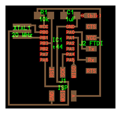
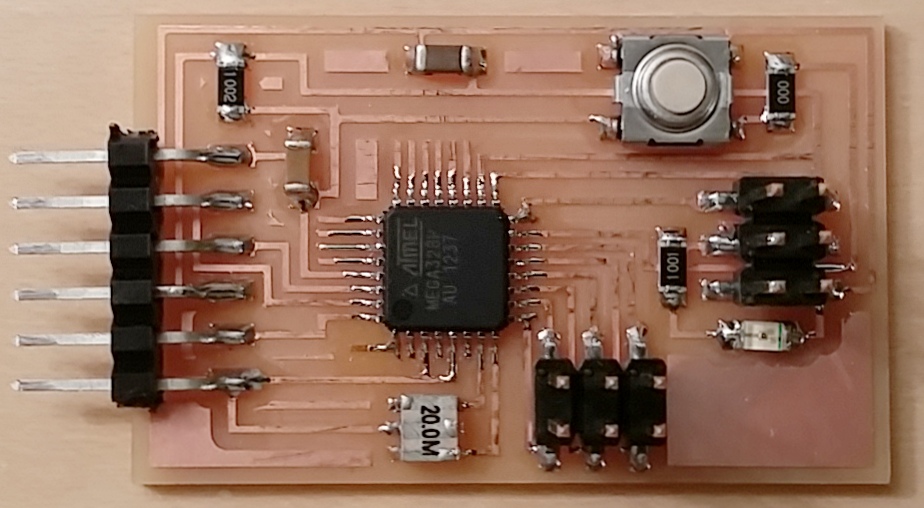
For this week we had to program an input device. Since My final project will need two types of inputs; (1)an object position: normal and upside down I wanted to use a magnet to trigger the read of the position. (2) My second input is a touchpad with 4 inputs. The board will also have 2 outputs (a screen and ESP826 for a wifi transmission of the information). Threfore I decided to make a version of my final board this week. I split the board into the main board with the Attiny44, ISPP header, FTDI header and a bujch of serial headers to connect inputs from differetn sensors. I also included a 20 MHz resonator to work with the ESP8266 in the future. Becasue the number of pins was a concern I used MISO, MOSI and SCK as inputs as well. To do that I used 4.7k ohm resistors between the pins of the Attiny44 and the sensors inputs.


The final stuffed boards are shown below.

And the wired boards are here.

Now for testing it I used a regular magnet. But before the testing can start we need to program it.
So the example provided was for an Attiny45 with internal 8 MhZ internal clock. The board I have is Attiny44 with external 20 MhZ resonator. We have a few changes to make to the make and c files.
The make file needs to be updated - in the header- for the clock (20 Mhz instead of 8 Mhz), the processor needs to be changed to attiny44 and we need to add the "fuses" lines to telle the processor to use an external clock.
Next moving to the C file.
We need to set the ports and directions. My input comes on PA6 so I need to:
#define serial_pin_out (1 << PA6)
Then in the main file we need to set the right A/D inputs:
ADMUX = (0 << REFS1) | (0 << REFS0) // Vcc ref
| (0 << ADLAR) // right adjust
| (0 << MUX3) | (0 << MUX2) | (0 << MUX1) | (0 << MUX0); // ADC0
Essentially these are the differences to make the C file work with the attiny44. For more information on how to set those ADC inputs, check out this link 1. Also for a step by step exaplanation on how to build a C code for link 2
Using the commercial AVR programmer on the ISP header I burned the program on the chip by typing the following:
$ sudo make -f hello.mag.44.make
$ $ sudo make -f hello.mag.44.make program-avrisp2-fuses
$ $ sudo make -f hello.mag.44.make program-avrisp2
Then to run the python script
$ python hello.mag.45.py /dev/tty.usbserial-AFYS1N9N
This is where the ADC input pins are set

This is to understand how the ADC input pins are set

And this is what you can read on the screen

- Date: November 2015
- Skills: Design, Milling and Soldering
- Time: 12 hours
Week 11
Interface Programming
1. Python Interface
Starting off with my input devices week I needed to build an interface for both the magnet and the touch pad. I started off with Neil's example (see input devices from the class site) to read the change in the value of the hall effect sensor with the magnet proximity. Python offers a convinient way to work with the devices through serial but for the charts display option there are other tools that are great. A few notes for working with python:
- Python 2.7 seems to be more stable (better supported by the community) than python 3.x.
- Install pyserial for serial communication
- Use a serial terminal to check that your devices are actually talking back, I used "CoolTerm"
- Use a python consol, I used "PyCharm" but also looked at Jupyter but did not get it to work (I suspect the different versions of python on my laptop were conflicting).
The best feature python gave me was to be able to VIEW the data coming out of the device and based on a condition on the data send an EMAIL. Python can also be used to open a websocket and pass data back and forth between a device and a web server (see Group project for more info on that.


#
# serial.read Nissia
#
import serial
import smtplib
from email.mime.text import MIMEText
#
import serial
ser=serial.Serial("/dev/tty.name of your port", 9600)
ser.setDTR()
buffer = []
while 1:
if ser.inWaiting():
#val = ser.readline(ser.inWaiting())
val=ord(ser.read())
buffer.append(val) # stores all data received into a list
print(val)
if val > 253:
USERNAME = "sender gmail address"
PASSWORD = "sender gmail password"
MAILTO = "receiver email"
msg = MIMEText('You have a new task')
msg['Subject'] = 'New Task'
msg['From'] = USERNAME
msg['To'] = MAILTO
server = smtplib.SMTP('smtp.gmail.com:587')
server.ehlo_or_helo_if_needed()
server.starttls()
server.ehlo_or_helo_if_needed()
server.login(USERNAME,PASSWORD)
server.sendmail(USERNAME, MAILTO, msg.as_string())
server.quit()
else:
# Here it does nothing, but you can call it with read operation.
del buffer[:]
2. Node Interface
With the node interface there are many more options as it allows for adding a web server and client feature. The same chart as in python can be displayed on html and a companion *.js file allows everything to be rendered in a web browser. Node opens a way for the web page to communicate with the device (through a websocket). To work with node you need the following:
- Install node
- Install npm, node's package manager
- Install node serialport
- Install node ws (websocket). A clarification (web socket are sockets talking to sockets through web websoket through socket talk to server).
- Navigate to the folder where you have both your project_name.js and your project_name.html and type "node project_name.js"

To test node with hardware I used an ESP8266 part from Adafruit also called the "Huzzah". The setup is very simple, Connect the FTDI cable from the computer to the board (as shown in the picture). Then use the tutorial provided on the class website . Once you start node you will see a screen like in the previous picture just use the set of commands to communicate with the ESP8266.


I had a few issues working with node mainly on the serial part. I was using brew to install (which looked like it was working) but upon starting node I was getting the following error message. I fixed it using direct install, then I kept running node and reading the error message until I had all the packages installed.
First error
Error: Cannot find module 'serialport'
Fix for error 1
home$ npm search serialport
home$ npm install serialport
Second error
listening for connections from 127.0.0.1 on 1234
module.js:340
throw err;
^
Error: Cannot find module 'ws'
Fix for error 2
home$ npm search ws
home$ npm install ws
In folder with js file
$ node hello.mag.44.js
An exampe of npm installation

- Date: November 2015
- Skills:Programming, Python, Node
- Time: 24 hours
Week 12
Thermoforming

Polycarbonate Thermoforming
I worked on a very simple version of composites with polycarbonate thermoforming. I needed a shell for my final project and initialy thought about 3D printing. But the given the size of my piece and the design, Justin recommednded thermofprming.
Before starting, with help from Justin, I tested the a scrap sheet of acrylic with a heat gun just to get a sense for what the thermofroming can give me. It was simple but the non-uniform heating did not work well for molding a unifrm shape.


After looking at a number of different plastics and the finished look I went with a clear polycarbonate (cut from scrap).
Since I had designed my shell in Rhino (see final project page), the very first step was to mill a "negative" mold in mdf to help the plastic form to the exact shape. I decided to test whther the Plycarbonate I had on hand was a good candidate and used a few tricks mold it manually.The process was fairly simple and less intimidating than I thought:
- Cut and clean a sheet of polycarbonate (ideally with the water jet but the table saw works too!)
- Cut four small pieces from the same material to calibrate the thermoforming machine (so it does not crush your sheet).
- Once the thermforming machine is at the right temperature, put your sheet and wait for 15-20 minutes.

As a bonus, this is a preview of a steel frame alternative.
- Once done, put on gloves and get the sheet out and put it on the top surface (IT IS HOT!).
- Form it using your mold or the next best thing (your hands and other tool that can handle heat).


Group Project
The Drink Machine

The User Interface
For the group project I worked on the front end interface to allow a user to order a particular drink mix from a web interface and a phone app.
I wanted to try using meteor as one of the nice features about it was that web and mobile interfaces are built at the same time. So first we need to download meteor and go through the tutorial (which is very well done).
It starts with a simple app for making your own to do list. There is also a seond example of a more elaborated app called market place. Once you install meteor you can just get the examples running by typing:
meteor create --example todos
or
meteor create --example todos


Meteor sets up everything automatically including a Mongodnb databse to store and query information from the website. In mongodb language Thre are collections (the lists of drinks in our case) and documents inside them (every single drink). This is an important definition to keep in mind for using Meteor and Mongodb as we will see later.
Finally the best thing about meteor is the deployment to a public site with a simple command
meteor deploy my_app_name.meteor.com

For the purpose of the group project I picked the to do list since with a few modifications it can be turned into a menu instead with the following steps:
- Edit the head and app body files (html and js) to adapt the style to our project. In our case it means no "sign" or "join" and only one list which our menu.
- Use python to open a websocket with meteor server. This last step was the most complex.
In a nutshell, to make python and meteor talsk to each other we need a meteor client for python. I used python-meteor , but ran into some complications and had to hardwire things into the python script (not very elegant).

- Date: December 2015
- Skills: Web programming
- Time: 40 hours
Final Project
Task Pad

1. The concept
The concept of my final project is to create a pad that sits on your desk and displays the tasks you have to do. The twist is that these tasks are sent you by your home appliances, these devices also send you emails reminders!
The appliances send you messages using magnets.Your regular fridge magnet will have two side CLEAN and DIRTY. If you walk by the friddge and notice it needs to be cleaned you touch or turn the magnet. A tiny chip inside the magnet detects the direction change and send an RF signal to your desk.

2. Design
For the design I used Fusion 360 from autodesk for the main panel. I had started playing with Fusion 360 a few weeks back but did not fully use it. The process was fairly simple and the rendering feature produces very nice results with the material and appearance options.
Overall Design


The front panel evolved from the 4 main tounch buttons to more defined icons representing "email seding". It also includes the four icons representing the appliances that can communicate with the front panel. The same icons on the fron panel are 3D printed while the actual front panel is laser cut from 1/4" acrylic. I used Rhino 3D for the design of the front panel and magnets.
Front Panel

Wireless Devices


3. Fabrication
The task pad has three main parts the support, the front panel and the magnets.
I used Thermoforming for the support with a 1/4" polycarbonate sheet. After cutting a rectangle on a band saw, and heating to the right temperature (See thermoforming week) I was able to form it to the desired shape. I used metal bending for the steel version of the support. After cutting the metallic sheet ont the water jet, filing the rough edges and bending the resulting shape is very close to the initial design. Initially I was thinking of using it as a forming mold but in fact it might be my v.2 model.
Support


The front panel was laser cut in balck 1/4" acrylic. I used the 70 watt laser at the lowest "reasonable" speed (10%) and highest power output (100%) and 3 passes.
Front Panel


The wireless enabled magnets that will reside on the appliances were 3D printed. As a test to see whether the size of the circuit would fit I used a drystone mold made during "Casting and Molding" week. the second alternative I considered was to print the circuit directly on a polycarbonate piece (vinyl cut circuit) and use it as a support for the circuit on one side and as a decorative magnet on the other side. In both cases it was tricky to fit everything in so I went with 3D printing. I vinyl cut a layer of copper tape to put on top of the 3D printed magnets to possibly use them as touch pads later on as well since (as we will see in the electronics section below), the hall effect sensor was not reliable enough for this application.
Wireless enabled magnets
Testing Different supports


Final 3D printed magnet support for Dishwasher


Final 3D printed magnet support for Fridge


3. Electronics
For the electronics boards I used the boards I designed during the "Input Devices" and "Output Devices" weeks as well as the "Networking" weeks.
Input Devices: Touch pad sensors with Tx-Rx and Hall effect Sensor. Designed with an Attiny44. I also included a serial header for communication with other boards.
Output Devices: LCD screen used with the default provided Attiny44. Reproduced from class and reprogrammed to read input from another board and display both static strings and dynamic values received from the other board.
Networking: Fabduinos boards with nRF24 modules to send and receive. Reproduced teh fabduino board from class but using Atmega 328 (not atmega 328p) and 20 MhZ resonator (not 16 MhZ). As we will see in the programming section, it took some effort to use this board with the Arduino IDE.
Input board for touch pad and Hall effect sensor


Networking boards

Output board


4. Programming
The touch pad sends an email to a pre-defined person when touched and displays a message on the LCD screen when it is sent. The appliances icons light up LED(s) when they receive a message fromt the wireless fridge and dishwasher magnets and the magnets send a message to the front panel when they are touched or a magnet is close by.
Touch pad board, hall effect board and LCD screen Attiny44 boards: Programmed with C, using an avrisp 2 and Crosspack suite.
Networking Atmega328 boards: Programmed using Arduino IDE after some major modifications in the Boards.txt and the avrdude.conf.
Device Interface


- Date: December 2015
- Skills: Web programming
- Time: 40 hours