3D Printing

This week we are 3D printing and scanning. As 3D printing is an additive fabrication technique, it works well for geometries with properties such as overhangs and nested components that you wouldn't be able to easily fabricate through subtractive methods.


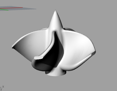
For my final project I'm planning on building a electric boat, and will likely 3D print a propellor using the Dimension, for a higher quality finish and so that it will be printed with ABS rather than PLA.

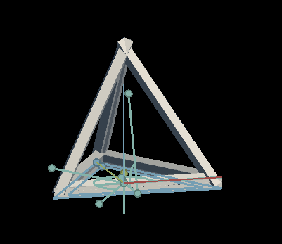
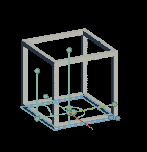
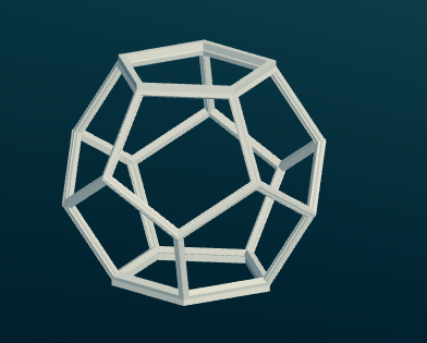
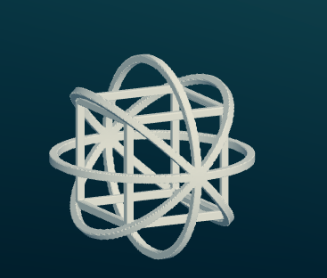
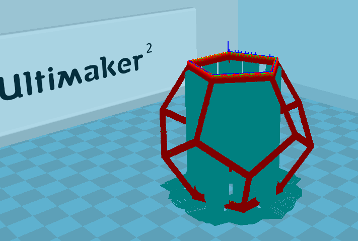
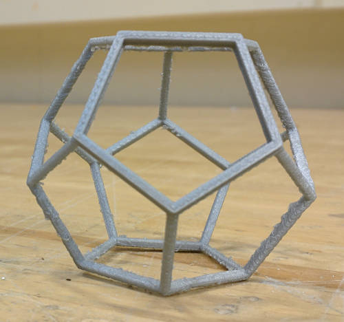
I have a solidworks file made by someone else that I can base my propellor design off of, so for this weeks assignment I just wanted to play with some geometric shapes. I started with the ambitious idea of wanting to make a 3D printed maze within a dodecahedron, but ran out of modeling time. Once again I'll be using antimony for my designs as it is nice and parametric, and through this exercise I picked up a few new tricks.

Geometry is Hard

Antimony makes N-sided 2d polygons that I used as the basis of my models. I decided to start with N=3 and work up to N=5 for my final shape. To construct my 3d geometries I started with the thinly extruded bottom face and rotate copies to create the final shape. You can see that the triangles don't meet up nicely at the top.

The cube looks much nicer, as the cross-sections of the edges of the shape are the same where they intersect (a square cross-section rotated 90 degrees is still a square!)

The dodecahedron turned out alright. Like the triangles above, there is some awkward overlapping along certain edges. It is less prominent however as the angles are not as severe. I also paid more careful attention to the geometry. In antimony the polygon size is determined by r, the radius of the circle that the points would define, so some trig is necessary to figure out edge lengths and positions.

I also modeled a cube within a sphere. This shape doesn't have the same issue with overlapping edges as the dodecahedron.

Lessons Learned

If I were to model the dodecahedron again I would try a different graph structure. For this model I started with an extruded face and then rotated a copy for each face. This made for edges that overlapped and did not meet up nicely. Instead, I think it would work better to first create a solid dodecahedron, shell it, and then cut out polygons from the faces leaving just the edges behind. This method should result in no funny unions at the edges.

Making the Toolpath

Each 3D printer has a different program associated with it that you can use to make the toolpath once you have an .stl. For the Ultimaker it is Cura. We were reccomended to use the fast print settings. The advanced options have a lot of options to tweak. You can see the support structure that it is going to build, and I chose the brim base.

The first few layers are the most important to watch. I needed to slow down my print job a little bit as the filament was not bonding well to each layer at the faster speed. The pieces were so flexible as they were being printed that the nozzle would make them jiggle as it was going past.

The print job took about 2 and a half hours. You can see the support structure in the middle. The aggressively overhung edges in the middle came out pretty well despite having no support structure. The edges are a lot thinner than I planned on making them, the printer seems to ignore features that were thinner than the nozzle (.4mm) and I think my geometry was not necessarily playing nicely.

The supporting structure is really easy to break away.

The final shape turned out pretty well. In the future I would be more careful generating the model. The edges on the faces were a little thin, but still came out pretty well. I could smooth them down with a soldering iron or heat gun if I wanted to.