Fabduino M1


I wanted to design my own Arduino compatible board for rapid prototyping and the ability to take advantage of some Arduino software libraries that exist for some of the components that I am planning on using in my final project. Even for projects not using the Arduino development platform, this board will obviously come in handy. Unlike some previous attempts I started off with 16MHz resonators and Atmega328P processors.
As to the name, there is already a Fabduino V2 out there, and then some people that have improved upon that board. Based on the types of connectors that are most availabile in the Architecture shop (ribbon cables rather than anything through hole), and that many of the modifications I was making could be seen as a step backwards from the other boards that have been developed, this is the Fabduino M1 (minus 1).
I went through a number of revisions which I won't detail here, but the final version has 12 input/output pins exposed through two 5x2 connectors. Each 5x2 connector also outputs 5V and 3.3V, along with two ground pins. The board can also be powered externially by 7-30V if you don't want to have an FTDI cable connected.
As this board is meant to be built with a 16 Mhz resonator and 328P processor it is very easy to configure within the Arduino development environment. Simply add the following to your boards.txt file.
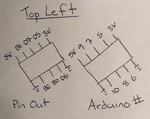
This is the processor pinout and arbitrary Arduino pin numbers for the output port at 45 degrees in the top left.
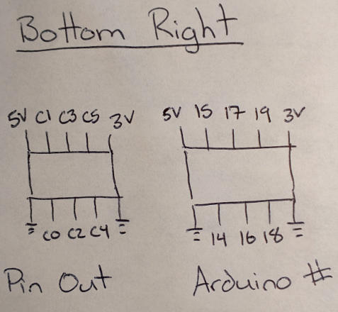
This is the processor pinout and arbitrary Arduino pin numbers for the outport port in the bottom right. The arduino output pins 14-19 also correspond to the arduino analogue input pins I0 to I5.