Output Devices
(with a little networking)
For my final project I want to have an OLED display on the top of my trekking pole, so I ordered a .96 monochrome OLED from adafruit and went to work. By default the OLED uses a software SPI interface, and Adafruit has some nice libraries developed for the Arduino Environment.
For the wireless networking I used two Addicore nRF24L01+ 2.4GHz wireless tranceivers. This is probably overkill for this project as they have a fairly long range, but they are well supported and still fairly low powered. As I plan on embedding them within the body of a pole, this should also help to ensure that they are sill able to send and receive to each other. The software libary and information on Arduino compatibility is available here.
OLED Demo
First I wired up the OLED screen to a connector cable and after a little debugging (one of the solder joints on my processor was no good) I was able to get the demo code that comes with the library running.
Networking Demo
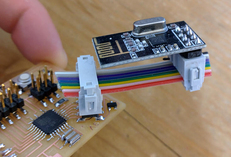
I made little connector cables to attach the nRF24L01+ units to my fabduino M1. This board is 5V logic tolerant, but wants 3.3V input, so this is where the 3.3V output from my board comes in handy. You can see that the board is wired up with just 8 of the 10 possible connectors, the two unused are the 5V/GND pair on the far left.
The library for the RF units came with some good example code. The units themselves are buffered, so it is simple to tell it to output some data, and then check on the other end to see if data has been retreived, and then grab it from the device if so. A response can be returned to confirm that the data made it through.