Week 5: Electronics Design
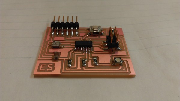
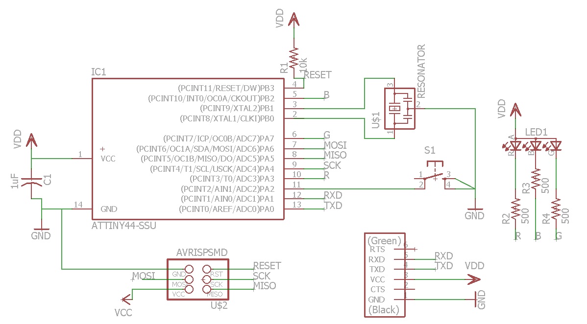
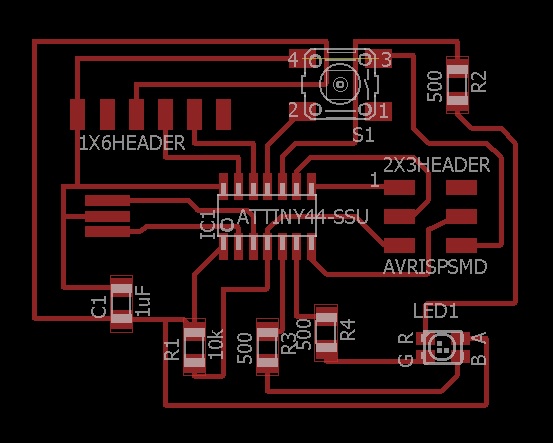
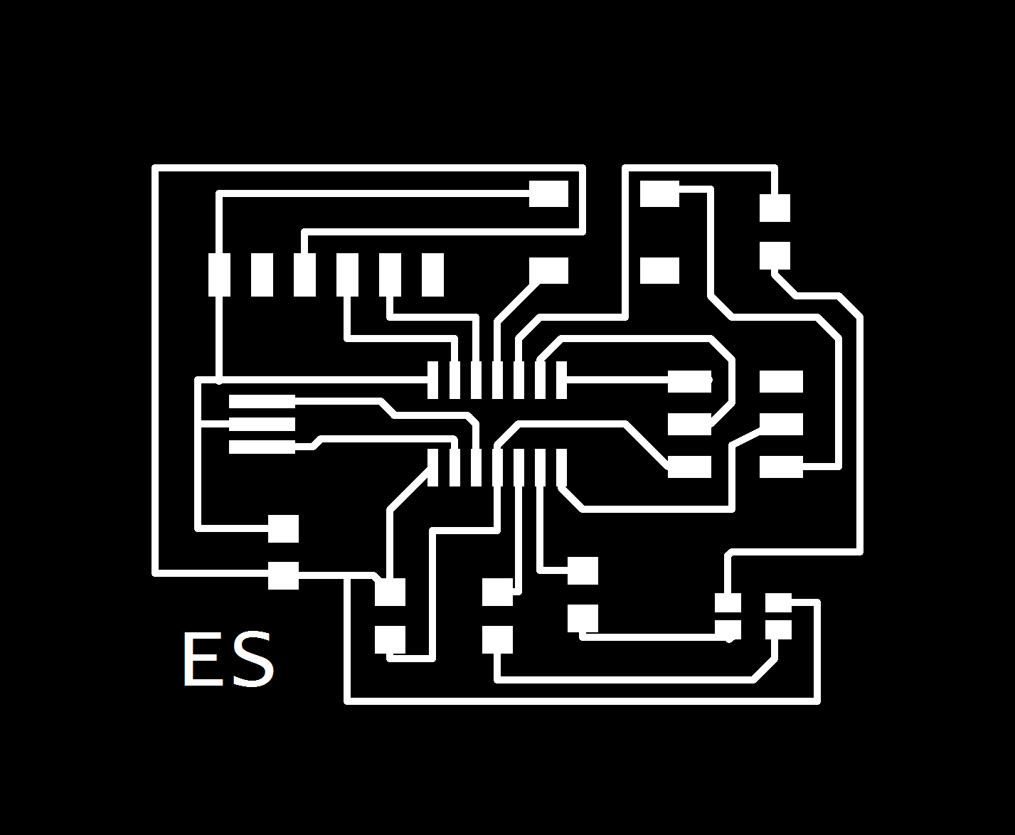
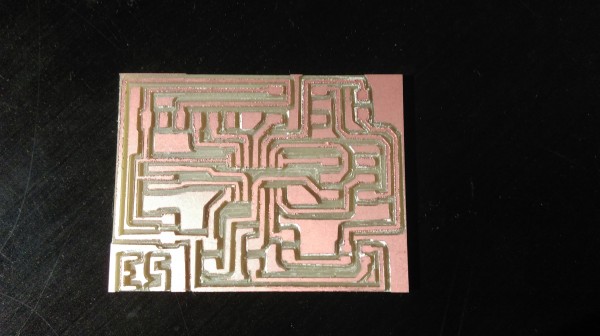
This week, we had to take a predesigned PCB, add an LED and button to the schematic, and then reroute and make the board. We had 4 pins free on the attiny44 microcontroller. First I decided to put the button on port A2, because one of its functions is a digital port. Then I decided to put an RGB LED on the remaining three pins. The RGB LED comes with three LEDs in one package. They have a shared anode, so I wired that to high and connected the RGB pins to the three empty microcontroller pins via resistors. The microcontroller will pull down the cathode of a given LED to turn it on. I haven't quite decided what I'll program my board to do, but I was thinking that I could have it do some sort of sequence or blending of the different colors when I press the button. I've included pictures of the schematic and the png files that I used to mill the boards. The first time I milled my board, I didn't export my png with the correct dpi, so the traces and wires were crooked and the wrong size. I then remilled it and it came out a lot nicer.