This project presented problems in two ways. The first is that I set out to learn another new CAD program Solidworks, which has quite a learning curve. The other was getting used to fiddling around with the options to “print” with the machines.
Vinyl Cutter
The biggest problem I had with the vinyl cutting assignment was choosing what design I wanted to create. I settled on a stylized design of the Peaucellier-Lipkin linkage, which was the first planar linkage invented that could convert pure rotary motion into pure linear motion. (Watt invented a linkage that was approximate, but functional.) The PL linkage has some interesting history and is quite beautiful.
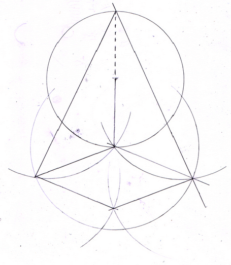
Hand Drawn Sketch
To do the design, I worked in Mathematica with its graphics capability. There was a lot of trial and error in this part with me working out the mathematics of the representation. As an update, I’d like to model this in Solidworks and see if I could manipulate it in a simulation. I think it would be a bit cooler if the mechanism was rotated upwards a bit so that the linkage was slanted diagonally from the bottom left to the top right. I also added portions that indicate where the linear and rotational motion occur.
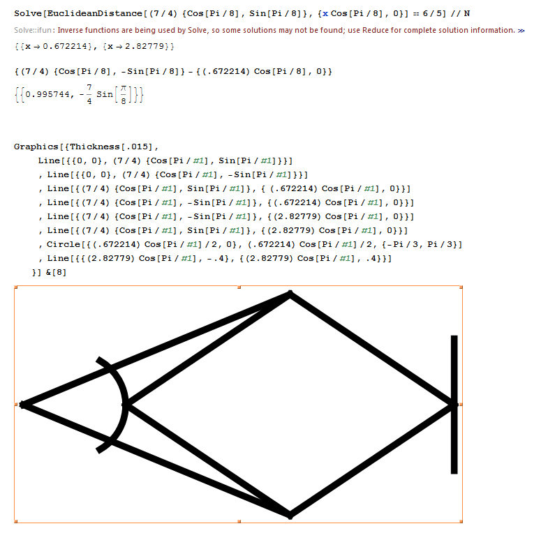
Code and Resultant Image
The actual cutting wasn’t too difficult. The setup of the vinyl cutter went well. The only hang up was that I had to adjust the force three times to get a cut all the way through the vinyl (40-80-120). One of the cool things I learned is that the vinyl cutter retains the origin until you tell it otherwise. The second iteration I did, I feed out the vinyl to examine the first cut and the, without readjusting, sent the design to the cutter again. I was worried that I was going to waste material, but the machine knew where it was located on the vinyl and retraced the same cut without my intervention. All of that makes sense, it just was unexpected.
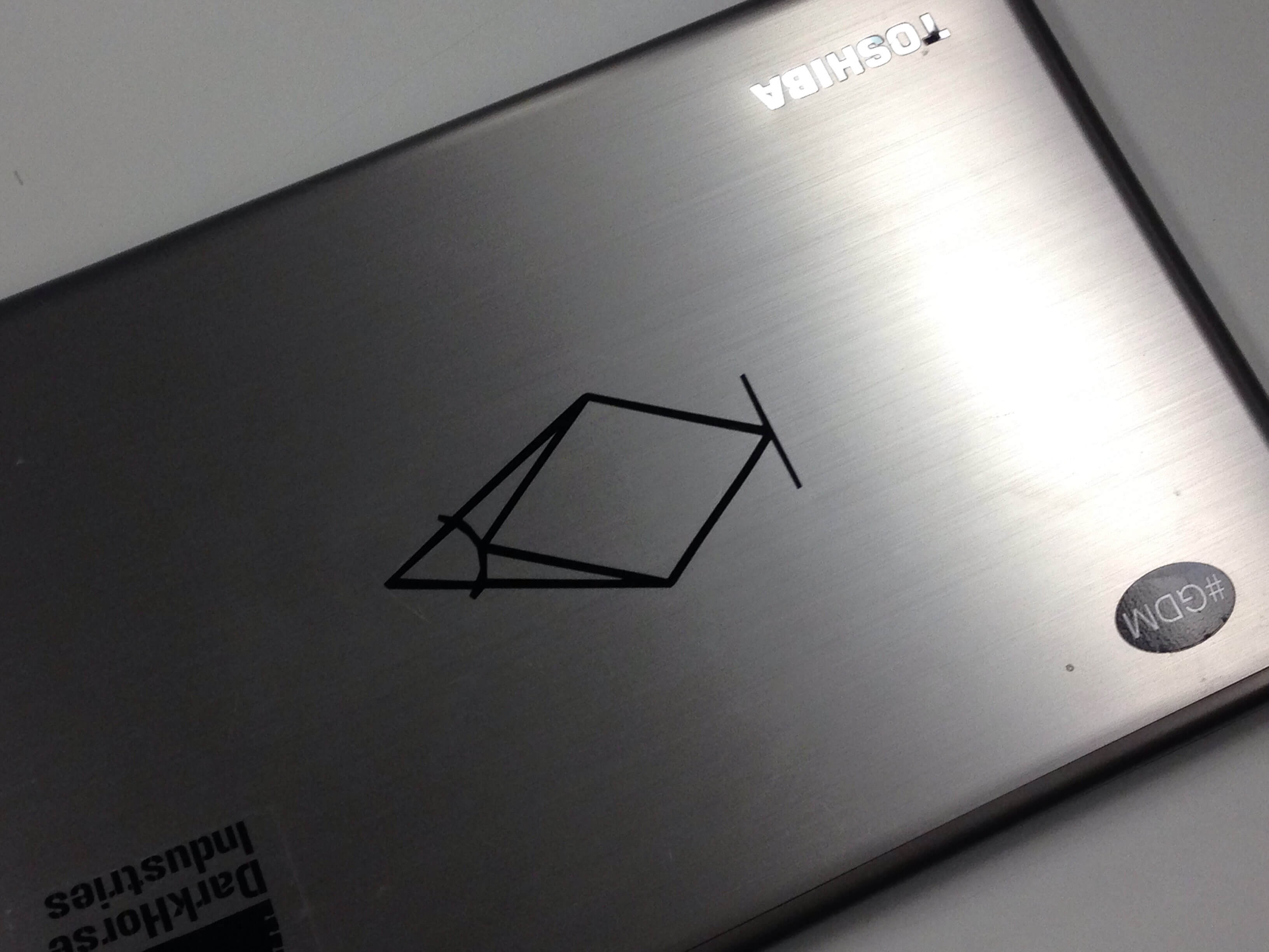
I think it came out well
Laser Cutting
My biggest struggle with this project was picking something to do. I tossed around a lot of ideas (gravity/diameter coin sorter, chess set, a wall bracket for a hammer, etc.), but in the end I decided on something more aligned with what Neil asked for, which was a press-fit construction kit that could be used to construct various things. This was a good call for a few reasons: 1) It was relatively simple, which was good because I’ve never used a laser cutter before 2) It met the needs of the project 3) It was somewhat nostalgic because I used to play with a press fit construction kit as a kid.
The first thing I did was start thinking about different shapes. I didn’t want to do something rectilinear because that’s boring. So I started working with circles in Antimony.
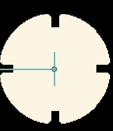
Initial shape
I wanted to create a diversity of pieces with different angles of rotation between the connecting joints, so that a diversity of structures could be created. The first problem I had was that I individually rotated all of the joints in the CAD file, which was inefficient in the parametric paradigm for creating different types of the base piece.
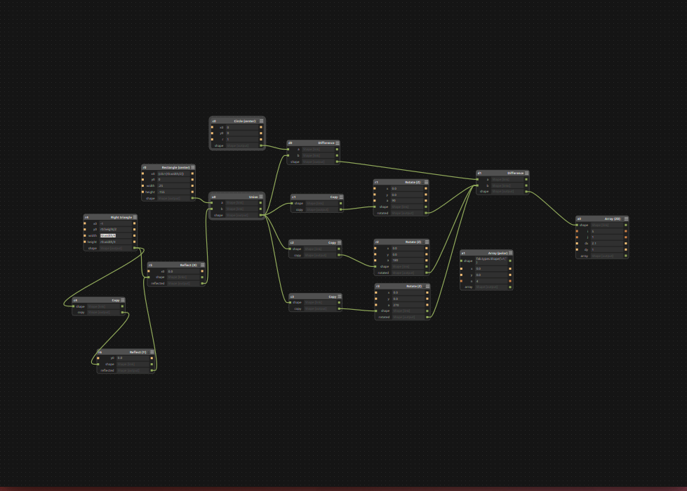
First draft of the template piece
I quickly found out that this was an inefficient way to draw the piece if I wanted to create a diversity of pieces. I restructured the graph to incorporate a polar array function and was able to create an array of pieces with different joint distributions throughout the body of the piece.
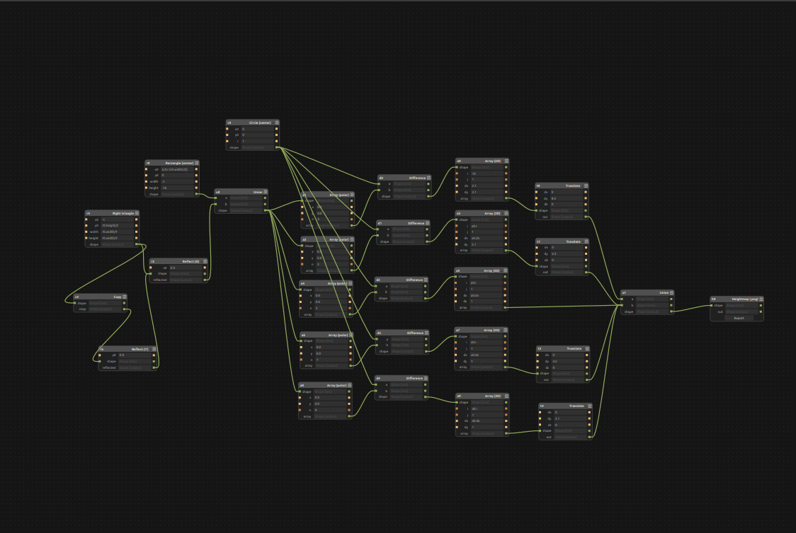
Second draft of the template piece
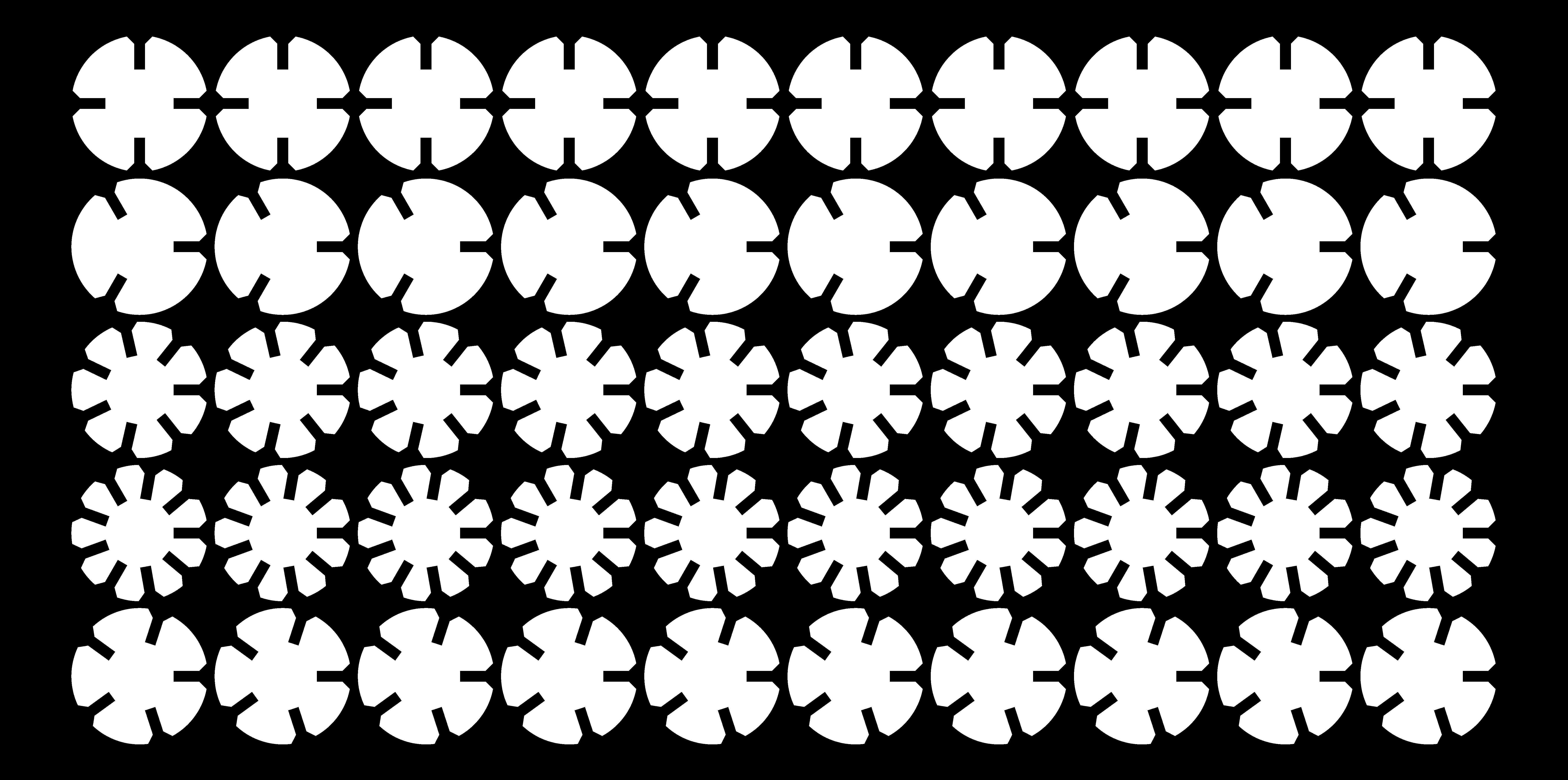
. . . and the result
So now we have a diversity of different pieces with different angles which should allow a lot of creativity in final construction. With a good working model, now I had to work out a workflow which would get the .png output from Antimony to a vector output that could be imported into Rhino for cutting.
A classmate told me about an automatic bitmap tracing function in a program called Inkscape, so off to google I went.
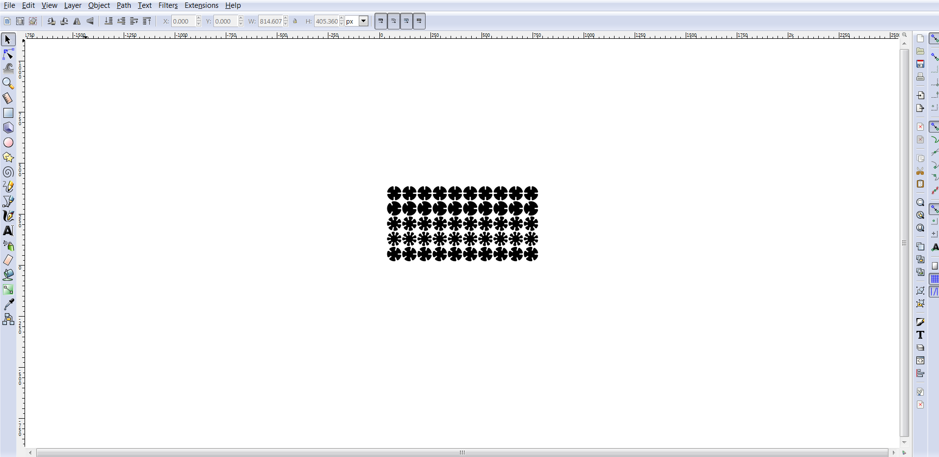
Inkscape traced image
After the Inkscape conversion it was then possible to export a vector image (in the form of a pdf) and import it into Rhino. In Rhino, it was pretty easy to use the print driver and set up the laser cutter to do the correct cuts. The real struggle with this workflow is that it requires the file to pass through three programs to get to the cutting step. Because of that, the iterative process of getting the joints to the correct size takes an inordinate amount of time. I could have probably cut down on this by using a different program to do the original design, but Antimony (as far as I can tell) is the best program I’ve found for doing parametric design in a very intuitive way.
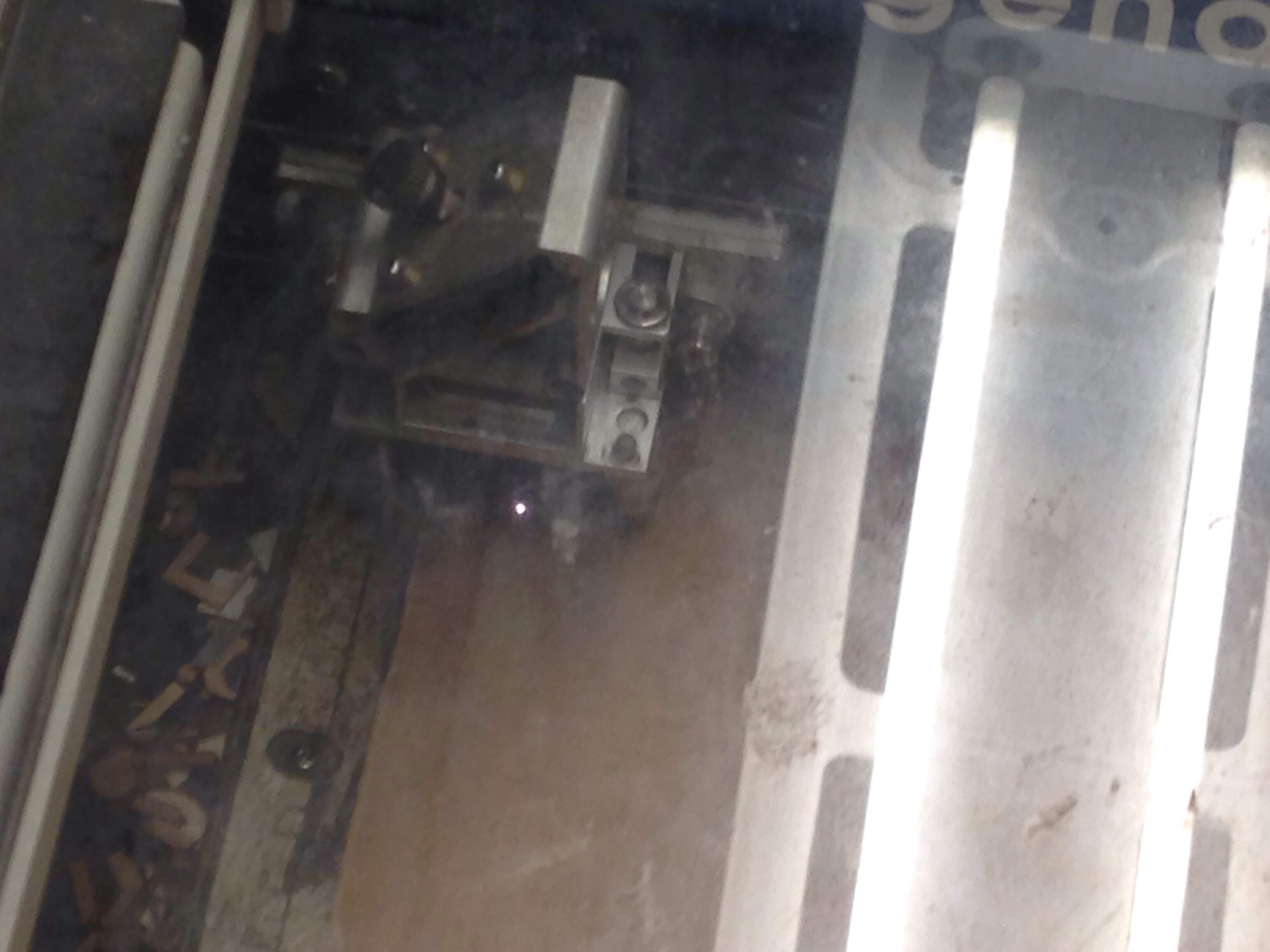
Laser cutter running
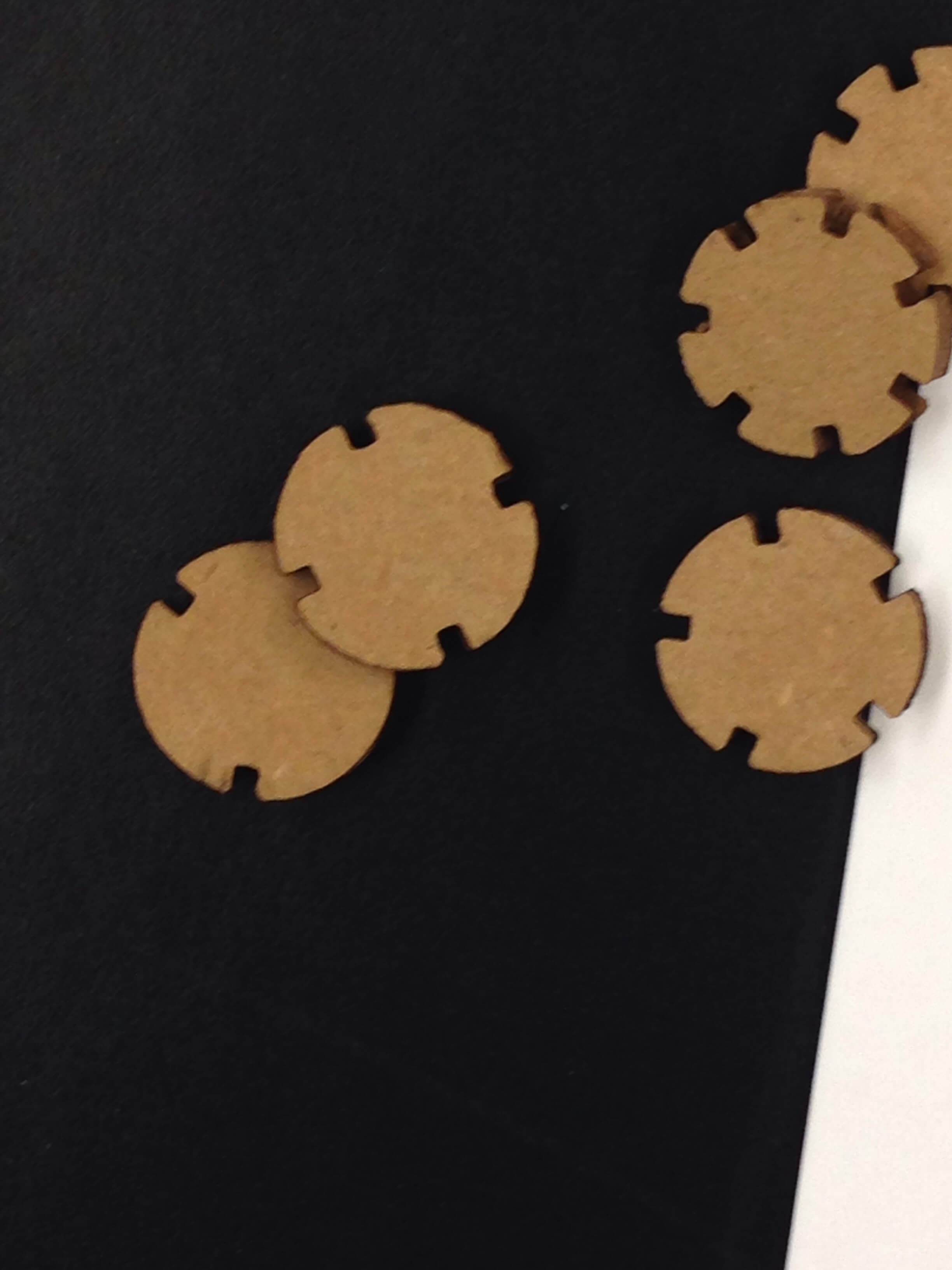
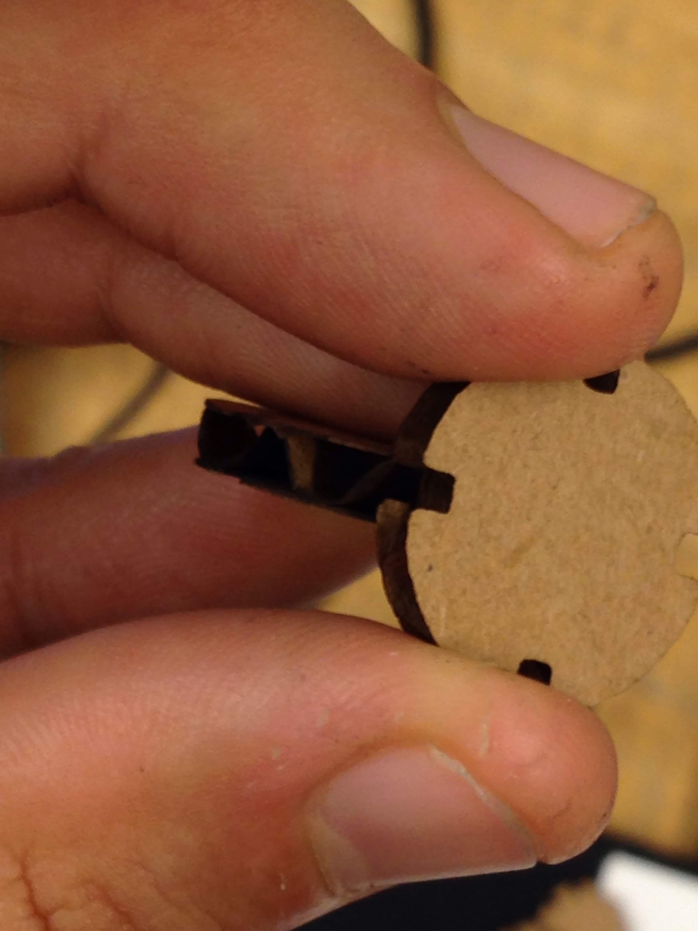
First iteration
The first test pieces had two problems with the joints. They clearly were not deep enough and they were just a hair off on width. Fortunately, that was pretty easy to change in Antimony. I’m still working on the next iteration.